Method of Forming a Heat Switch

a heat switch and gas gap technology, applied in the field of cryogenics, can solve the problems of difficult manufacturing of high-performance switches using interdigitated design, poor heat transfer properties, and no heat transfer path available, and achieve excellent heat transfer, high integrity and strength, and robust joints.

Active Publication Date: 2019-11-07
OXFORD INSTR NANOTECH TOOLS
View PDF0 Cites 0 Cited by
  • Summary
  • Abstract
  • Description
  • Claims
  • Application Information

AI Technical Summary

Benefits of technology

[0027]Most typically, the gap is less than 0.05% the sum of the dimensions of the conductors along the major axis between a respective point of joining of the first conductors with the first connecting member and the second conductor with the second connecting member. As the conductors and the connecting members may have multiple points of joining, or an extensive join region, the relevant point of joining is nearest to the proximal end of the respective conductor. It is this point which provides the zero mutual strain position between the joined components with respect to which the relative differential thermal contraction occurs. Conductors having dimensions along the major axis of the order of several centimetre...

Problems solved by technology

The switch is opened by evacuating the gas from the chamber so that this heat transfer path is no longer available.
It is relatively difficult to manufacture a high performance switch using the interdigitated design, partic...

Method used


Image

  • Method of Forming a Heat Switch
  • Method of Forming a Heat Switch
  • Method of Forming a Heat Switch

Examples


Embodiment Construction

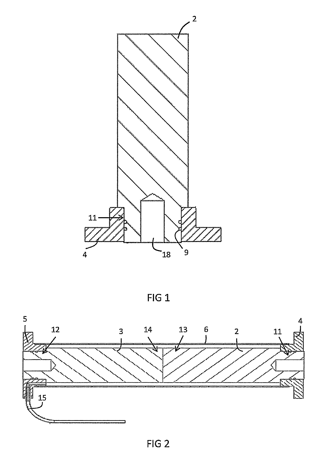
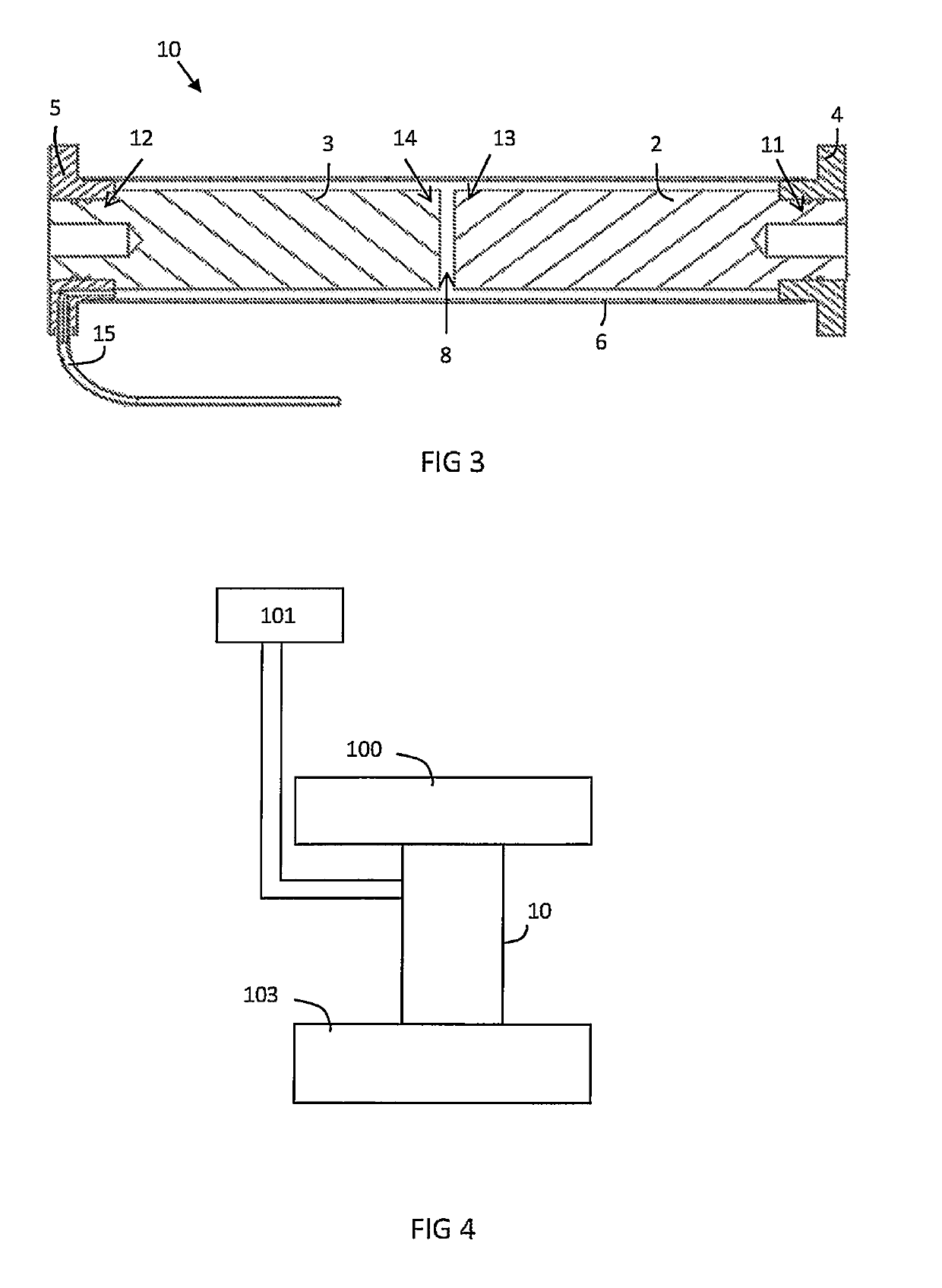
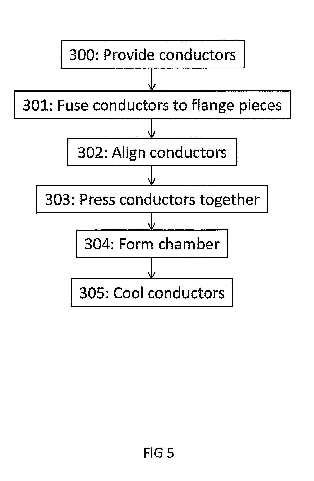
[0056]An embodiment of a method for forming a thermal contraction gas gap heat switch 10, as well as an embodiment of this switch 10, will be discussed with reference to the flow chart of FIG. 5 as well as the accompanying drawings of FIGS. 1 to 3.

[0057]First and second conductors 2, 3 are provided at step 300 of FIG. 5. A sectional view of a first conductor 2 and a first connecting member in the form of a first flange 4 is provided in FIG. 1. The first conductor 2 is elongate and substantially cylindrical. The first flange 4 comprises a central bore with a diameter of about 1 cm, which engages with a first end portion 11 of the first conductor 2. The first end portion 11 has a diameter of 1 cm along its length, whereas the remainder of the conductor 2 has a larger constant diameter of 2 cm along its length, such that the first flange 4 is fitted onto and around the first end portion 11 only as a collar. The first end portion 11 comprises a central bore 18 for enabling a physical co...


PUM


Abstract

A method for forming a gas gap heat switch is provided comprising the following steps: (a) providing first and second conductors, and first and second connecting members, wherein the connecting members each have a thermal conductivity at least five times smaller than that of the conductors when at a temperature of 100K; (b) fusing the first conductor to the first connecting member and the second conductor to the second connecting member; (c) aligning the conductors such that the first and second conductors extend along a common major axis; (d) bringing proximal ends of the aligned conductors into contact with each other when said conductors are at a first temperature; and (e) joining the first connecting member to the second connecting member so as to form a chamber around at least the proximal ends of the conductors. The connecting members forming the chamber each have a coefficient of thermal expansion that is less than that of the conductors such that, when the conductors are cooled to a second temperature which is below the first temperature, the length of the conductors along the major axis decreases with respect to the length of the chamber along the major axis so as to form a gap between the proximal ends of the conductors. The switch is also arranged to selectively provide a thermally conductive gas into the chamber when in use to cause operation of the switch.

Description

FIELD OF THE INVENTION[0001]The present invention relates to the field of cryogenics and, in particular, to a method for forming a gas gap heat switch.BACKGROUND TO THE INVENTION[0002]Gas gap heat switches (or “thermal switches”) are known in the field of cryogenics and are particularly useful in ‘cryogen-free’ systems, where the cooling is provided by closed cycle mechanical coolers rather than liquefied gases. These switches may be controlled to transfer or isolate a thermal load from one end of the switch to the other. In general they comprise at least two conductors which are separated from each other within a chamber into which a gas can be introduced. When the switch is closed, the gas inside the chamber facilitates heat transfer between the conductors by conduction. The switch is opened by evacuating the gas from the chamber so that this heat transfer path is no longer available.[0003]The conductors typically take the form of interleaving or Interdigitated' members, for examp...

Claims


Application Information

Patent Timeline
IPC IPC(8): F25D19/00F28F13/00F25B21/00
CPCF28F2013/008F25D19/006F28F13/00F25B21/00F16L59/00F17C13/00F25B13/00G05D23/00
Inventor MATTHEWS, ANTHONY
Owner OXFORD INSTR NANOTECH TOOLS
Why Eureka
Try Eureka