
Optical Ring Circuit with Electrical Filter

a technology filter, applied in the field of optical ring circuit with electrical filter, can solve the problems of large optical loss, signal distortion from trailing edge, ring modulator suffering from trailing edge distortion,

Active Publication Date: 2019-11-07
MITSUBISHI ELECTRIC CORP
View PDF9 Cites 2 Cited by
  • Summary
  • Abstract
  • Description
  • Claims
  • Application Information

AI Technical Summary

Benefits of technology

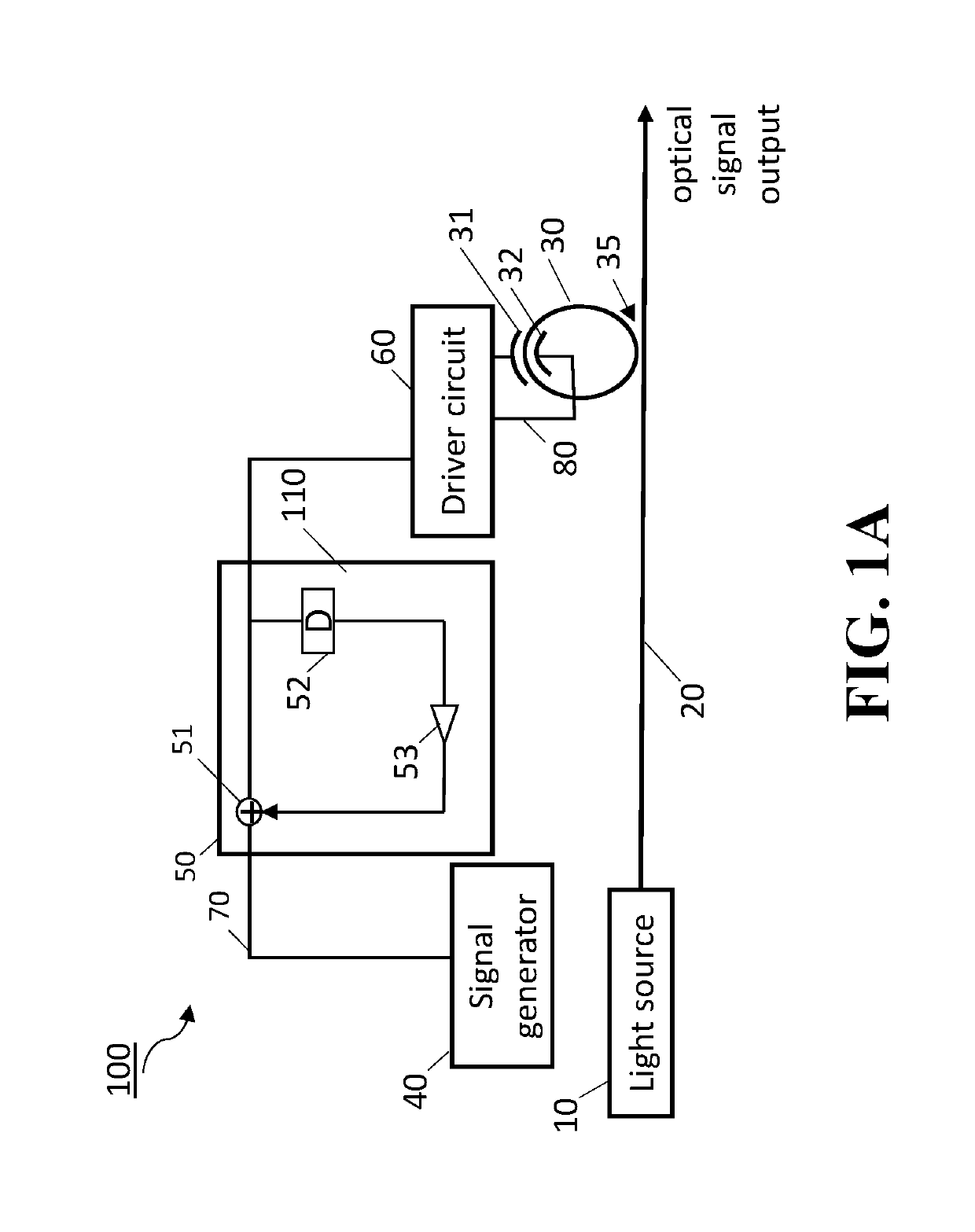
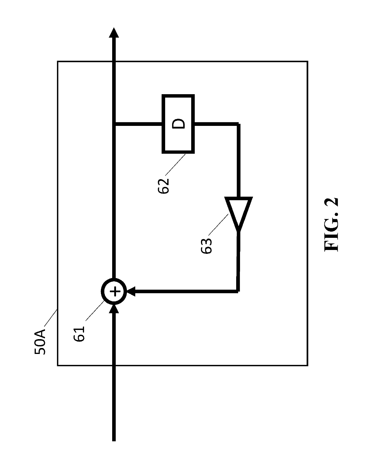
The patent suggests that distortion in the output signal of an optical ring circuit can be improved by using an electric signal with a slow variation. This improvement can be achieved by using an Infinite Impulse Response (IIR) filter or a Finite Impulse Response (FIR) filter. The technical effect of this invention is to improve the quality of optical signal processing.

Problems solved by technology

Although they do not have inherent optical bandwidth limitation, their very long waveguides as well as a pair of 3 dB couplers contribute to large optical loss.
However, ring modulator suffers from trailing edge distortion due to the memory effect of the ring modulator, because the light recirculates in the ring during modulation and a small amount of modulated output remains even after the modulation signal disappears, causing signal distortion from a trailing edge.
However, heavily distorted signals cannot be fully compensated due to the limited range of analog-to-digital converters and following signal processing circuit.
The receiver-side compensation also heavily increases part of the frequency component of the noise, leading to degraded signal quality.

Method used


Image

  • Optical Ring Circuit with Electrical Filter
  • Optical Ring Circuit with Electrical Filter
  • Optical Ring Circuit with Electrical Filter

Examples


Embodiment Construction

[0021]The following description provides exemplary embodiments only, and is not intended to limit the scope, applicability, or configuration of the disclosure. Rather, the following description of the exemplary embodiments will provide those skilled in the art with an enabling description for implementing one or more exemplary embodiments. Contemplated are various changes that may be made in the function and arrangement of elements without departing from the spirit and scope of the subject matter disclosed as set forth in the appended claims.

[0022]Specific details are given in the following description to provide a thorough understanding of the embodiments. However, understood by one of ordinary skill in the art can be that the embodiments may be practiced without these specific details. For example, systems, processes, and other elements in the subject matter disclosed may be shown as components in block diagram form in order not to obscure the embodiments in unnecessary detail. In...


PUM


Abstract

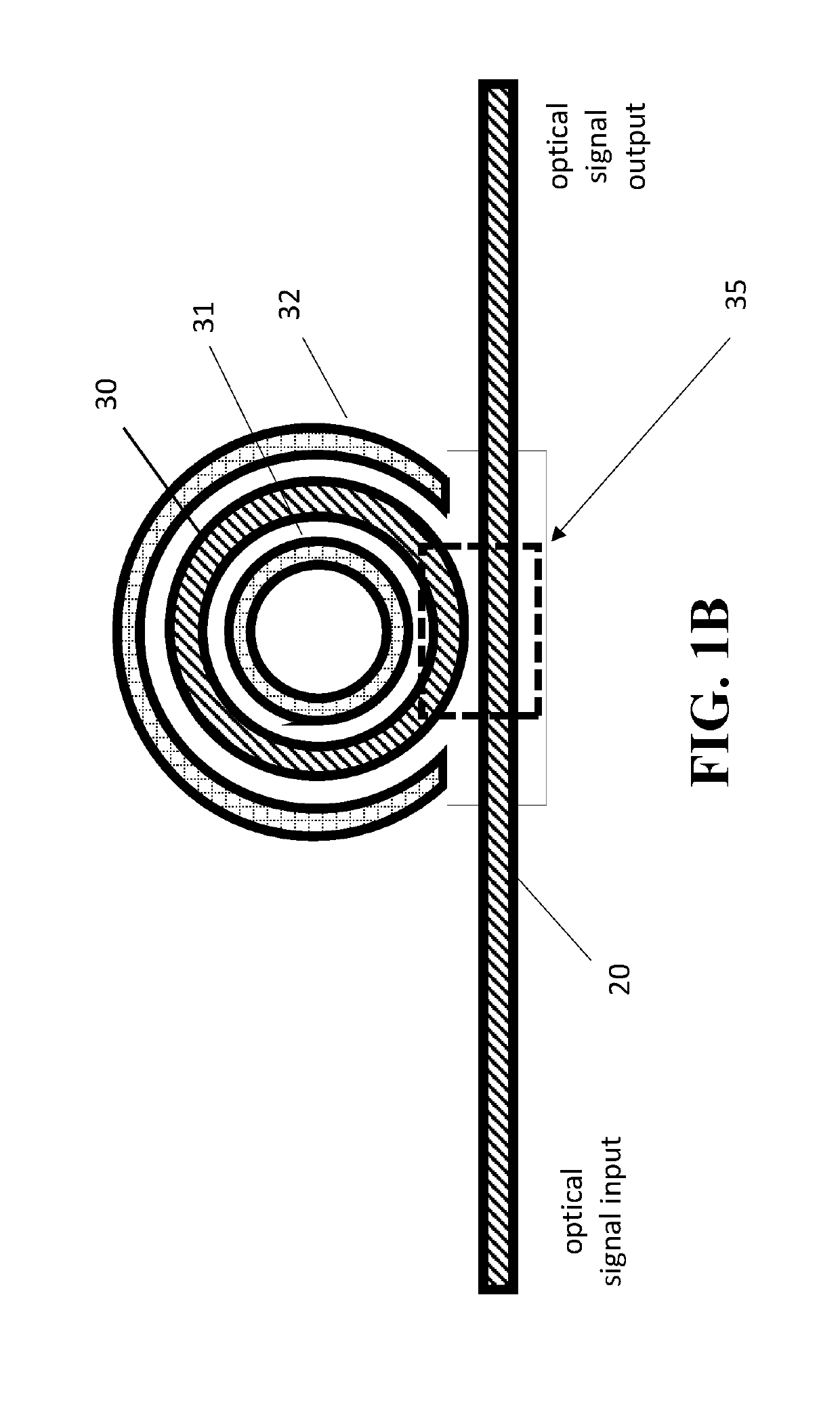
An optical ring circuit for modulating light from a light source into an optical signal includes a ring modulator located near a waveguide to couple a light propagating the waveguide, the ring modulator including a pair of electrodes, a signal generator to transmit an electrical signal corresponding to the optical signal, a filter circuit to generate an output signal, wherein the filter circuit includes an adder unit and at least one tap unit having a delay unit and a coefficient unit, wherein the adder unit adds the electrical signal from the signal generator and a signal passed from the tap unit for pre-compensating signal components of the electrical signal by at least twice delay time of the delay unit, and a driver circuit to apply a voltage to the electrodes based on the output signal.

Description

FIELD OF THE INVENTION[0001]This invention generally relates to Optical ring circuit with electrical filter.BACKGROUND OF THE INVENTION[0002]Mach-Zehnder modulators are widely used modulator used for high-speed optical communications, and are nearly ideal in terms of modulation characteristics. The basic principle is to accumulate phase shift along mm long Mach-Zehnder arms, which dictates its very large footprint. Although they do not have inherent optical bandwidth limitation, their very long waveguides as well as a pair of 3 dB couplers contribute to large optical loss.[0003]On the other hand, optical ring modulators are compact modulators and are suitable for photonic integrated circuits. In these modulators, phase shift can be amplified by the cavity resonance effect without relying on long distance propagation. However, ring modulator suffers from trailing edge distortion due to the memory effect of the ring modulator, because the light recirculates in the ring during modulati...

Claims


Application Information

Patent Timeline
IPC IPC(8): G02F1/225H03H17/04H03H17/06
CPCH03H17/06G02F1/2257H03H17/04G02F1/0121G02F2203/15
Inventor KOJIMA, KEISUKETENG, MINKOIKE-AKINO, TOSHIAKILIN, CHUNGWEIPARSONS, KIERANGOTODA, MITSUNOBUAKIYAMA, KOICHI
Owner MITSUBISHI ELECTRIC CORP
Learn More