Drop-Shaped Brush Head Assembly

a brush head and drop-shaped technology, applied in the field of brushes, can solve the problems of difficulty in controlling the operating angle of the brush, the amount of paint required, and the need to clean the paint left in the bristles frequently

Inactive Publication Date: 2019-11-21
ALLEN & THOMAS COSMETIC ACCESSORIES
View PDF2 Cites 0 Cited by
  • Summary
  • Abstract
  • Description
  • Claims
  • Application Information

AI Technical Summary

Benefits of technology

[0012]A piston rod is mounted in the mounting space of the drop-shaped brush head. The piston rod is connected to a sleeve and an elastic member is disposed between the piston rod and the sleeve. Thus the drop-shaped brush head assembly is movable in the axial direction. At least one discharge hole is radially passed through the

Problems solved by technology

The operating angle of the brush is difficult to control while using the brush to paint tiny area.
Besides

Method used


Image

  • Drop-Shaped Brush Head Assembly
  • Drop-Shaped Brush Head Assembly
  • Drop-Shaped Brush Head Assembly

Examples


Embodiment Construction

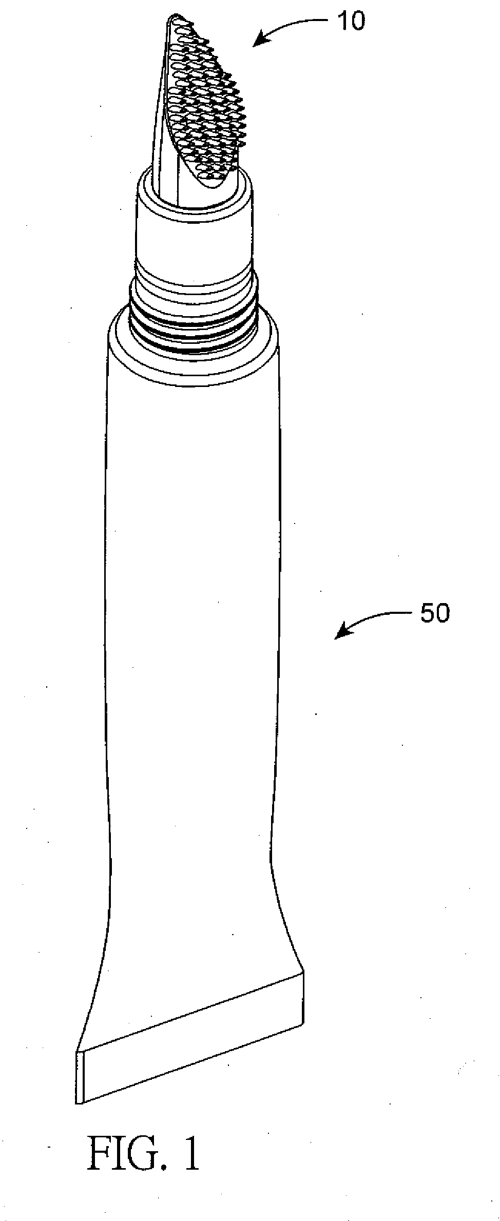
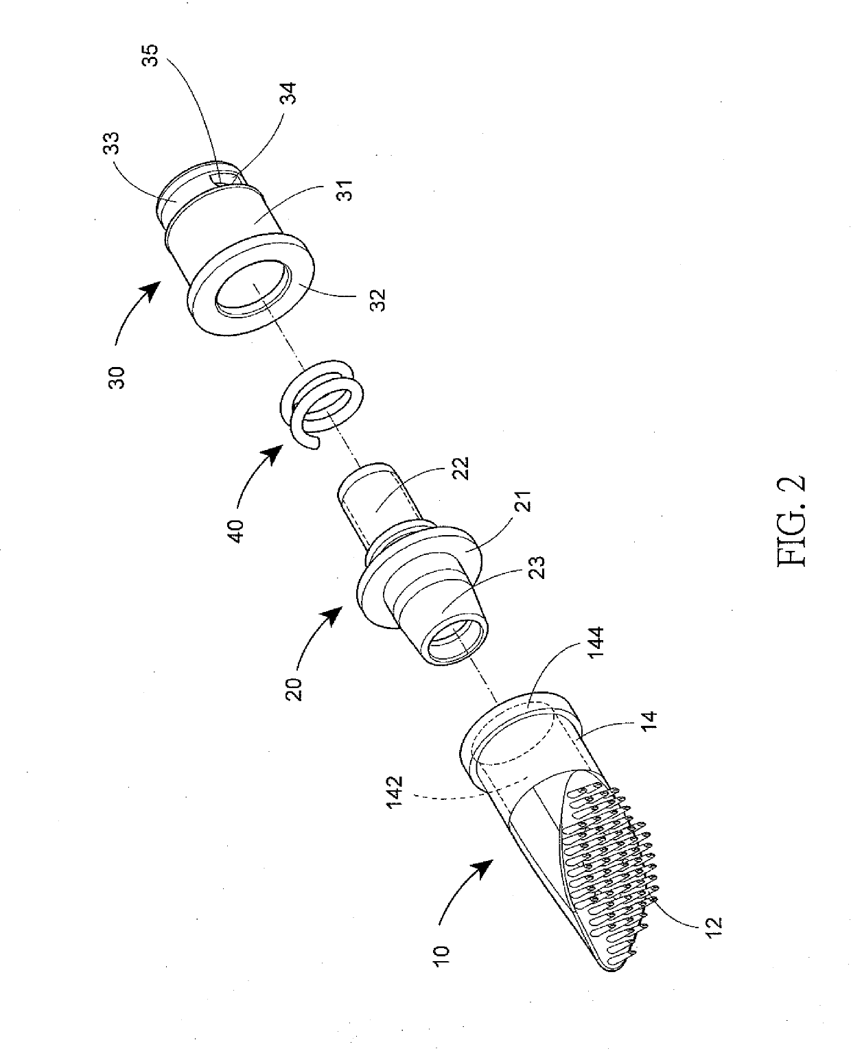
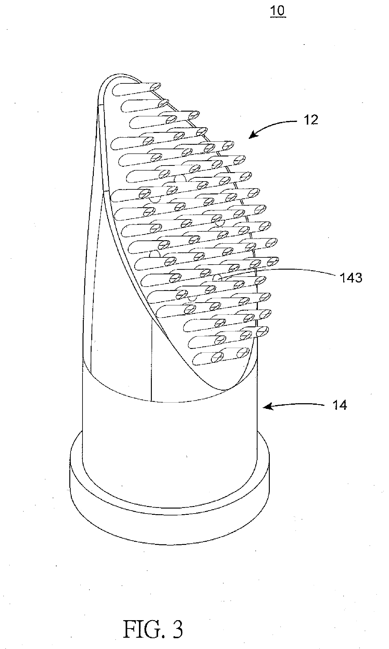
[0021]Refer to FIG. 1 and FIG. 2; a drop-shaped brush head assembly with an inclined cutting plane (oblique section plane) is revealed. The drop-shaped brush head assembly includes a drop-shaped brush head 10, a hollow piston rod 20, and a hollow sleeve 30. A mounting space 142 is arranged at the drop-shaped brush head 10 and the hollow piston rod 20 is mounted in the mounting space 142. The piston rod 20 includes a leaning portion 21, a rod body 22 extended from one end of the leaning portion 21 and a fixing portion 23 extended from and arranged at the other end of the leaning portion 21. The hollow sleeve 30 is mounted on the rod body 22 of the piston rod 20 and an elastic member 40 is disposed between the piston rod 20 and the sleeve 30. The sleeve 30 consists of a shaft body 31, a conical bottom portion 33 tapered from one end of the shaft body 31, a circular flange 32 extended outward and arranged at the other end of the shaft body 31, at least one discharge opening 34 radially...


PUM


Abstract

A drop-shaped brush head assembly is revealed. The drop-shaped brush head assembly includes a drop-shaped brush head which is formed by a plurality of bristles and a handle connected to each other. The bristles are used for combing hair and the handle is for support. The handle consists of a plurality of discharge holes on top thereof and a mounting space therein. A paint in the mounting space flows through the discharge holes of the handle and the bristles to be applied to target area. The drop-shaped design of the brush head has a pointy end on top and a larger end on bottom thereof. The pointy end allows users to control the operating angle easily while grooming fine-hair area and the larger end is used to apply the paint to large area conveniently. Thereby the brush head assembly is more convenient to use.

Description

BACKGROUND OF THE INVENTIONField of the Invention[0001]The present invention relates to a brush, especially to a drop-shaped brush head assembly with an inclined cutting plane.Description of Related Art[0002]A brush available on the market includes a flat surface on top thereof and a bundle of bristles is disposed over a holder. The operating angle of the brush is difficult to control while using the brush to paint tiny area. Moreover, the bristles are collected in a bundle so that a paint discharged from a discharge hole flows along the bristles. However, the bristles are closely attached to each other. Thus the bristles hold more amount of the paint through capillary action while applying the paint with the brush. Besides the increased amount of the paint required, the paint left in the bristles has to be cleaned frequently. Thus there is room for improvement and there is a need to provide a novel structure of the brush head assembly.SUMMARY OF THE INVENTION[0003]Therefore it is a...

Claims


Application Information

Patent Timeline
IPC IPC(8): A46B11/00A46B9/02A46B1/00A46B17/04
CPCA46B17/04A46B11/0006A46B9/028A46B9/025A46B1/00A46B11/0055A46B2200/1066
Inventor LIU, LI-MEI
Owner ALLEN & THOMAS COSMETIC ACCESSORIES
Why Eureka
Try Eureka