
Rotating latch assembly for raising and lowering the height of a vehicle

a technology of latch assembly and vehicle, which is applied in the direction of vehicle springs, resilient suspensions, vehicle components, etc., can solve the problems of constant hydraulic pressure and periodic work/restart of hydraulic pumps, so as to reduce air drag, improve vehicle energy consumption, and efficiently raise and lower vehicle heights

Active Publication Date: 2019-11-21
BEIJINGWEST INDUSTRIES
View PDF0 Cites 0 Cited by
  • Summary
  • Abstract
  • Description
  • Claims
  • Application Information

AI Technical Summary

Benefits of technology

The present invention is a rotating latch assembly for vehicles that efficiently raises and lowers the vehicle, which reduces energy consumption due to air drag. The assembly keeps the vehicle in the raised position without additional energy consumption and prevents unintentional movements. It includes a lift housing and a support tube that move between an extended position and a lowered position to raise or lower the vehicle. The assembly also includes a retaining member to keep the lift housing in the extended position and allow it to move between the extended and lowered positions. Overall, this invention improves energy efficiency and reduces air drag in vehicles.

Problems solved by technology

However, if the lift housing needs to be held in an extended position to increase the height of a vehicle, a constant hydraulic pressure is required.
Accordingly, the hydraulic pump needs to work / restart periodically due to unavoidable internal leaks.
However, the solenoid activated mechanisms require electric power input for the locking / unlocking of the solenoid valve which cumulates with the required hydraulic power.

Method used


Image

  • Rotating latch assembly for raising and lowering the height of a vehicle
  • Rotating latch assembly for raising and lowering the height of a vehicle
  • Rotating latch assembly for raising and lowering the height of a vehicle

Examples


Embodiment Construction

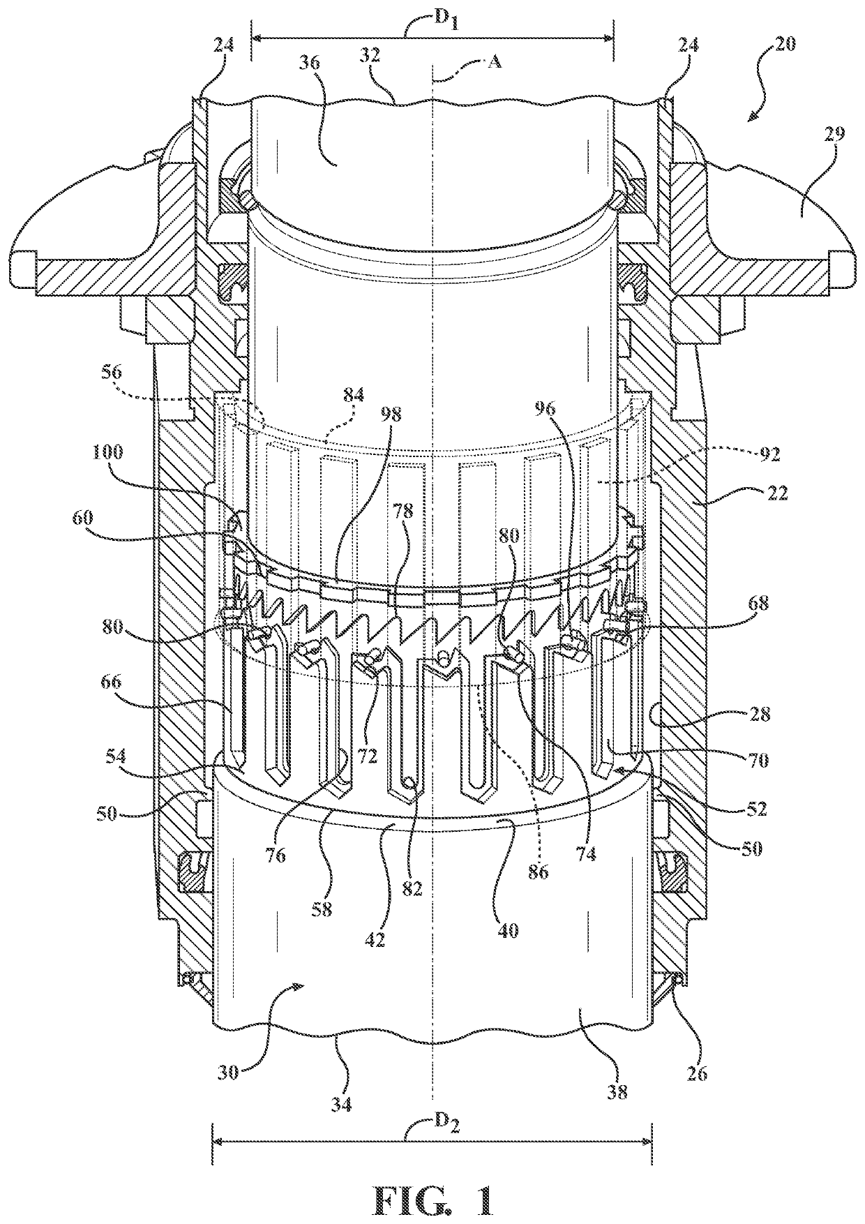
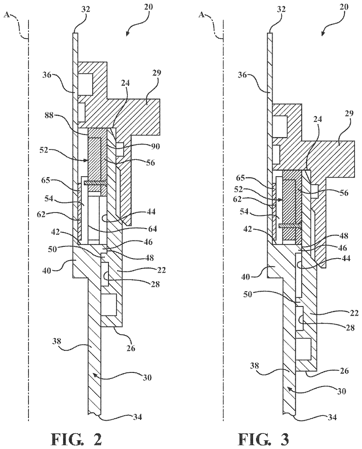
[0018]Referring to the Figures, wherein like numerals indicate corresponding parts throughout the several views, a rotating latch assembly 20 constructed in accordance with one embodiment of the present invention is generally shown in FIG. 1. Typically, the rotating latch assembly 20 is used in a vehicle for raising and lowering the height of the vehicle.

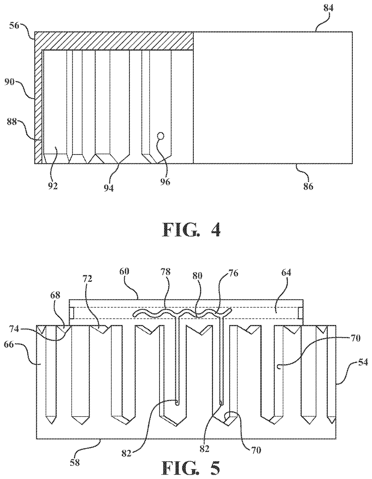
[0019]As best shown in FIG. 1, the rotating latch assembly 20 includes a lift housing 22, having a generally tubular shape, disposed annularly about and extending along a center axis A between a first opened end 24 and a second opened end 26. The lift housing 22 defines a chamber 28 extending along the center axis A between the first opened end 24 and the second opened end 26. A lift springs seat 29 is disposed about the first opened end 24 of the lift housing 22 and extends annularly about the center axis A. A support tube 30, having a generally cylindrical shape, is disposed in the chamber 28 of the lift housing 22. The support tu...


PUM


Abstract

A rotating latch assembly includes a lift housing extending between a first opened end and a second opened end and defining a chamber extending therebetween. A support tube is slidably disposed in the chamber and extends between a first end and a second end. The lift housing is movable along the support tube between an extended position and a lowered position in response to a movement provided by an actuator wherein the extended position is the lift housing being adjacent to the first end and the lowered position is the lowered position being adjacent to the second end. A retaining member is disposed between the lift housing and the support tube and attached to the support tube and the lift housing for maintaining the lift housing in the extended position as the lift housing moving from the lowered position to the extended position.

Description

CROSS-REFERENCE TO RELATED APPLICATIONS[0001]This application claims the benefit of U.S. Provisional Application Patent Ser. No. 62 / 674,588, filed May 21, 2018, the entire disclosure of which is hereby incorporated herein by reference.BACKGROUND OF THE INVENTION1. Field of the Invention[0002]The present invention generally relates to a rotating latch assembly for raising and lowering the height of a vehicle.2. Description of the Prior Art[0003]Devices for adjusting the height of a vehicle body are known. The devices may be provided in the suspension struts of motor vehicles, in particular, for increasing the ground clearance of motor vehicles or lowering the body for flat road surfaces. Typically, such a device includes a lift housing disposed on a center axis defining a chamber. A support tube is disposed in the chamber with the lift housing being movable along the center axis relative to the support tube. The movement of the lift housing is typically conducted using a hydraulic ac...

Claims


Application Information

Patent Timeline
Patent Type & Authority Applications(United States)
IPC IPC(8): B60G17/015B60G17/005
CPCB60G2500/30B60G2204/44B60G2202/42B60G2204/4604B60G17/0157B60G17/005B60G11/16B60G15/06B60G17/021B60G2202/441B60G2204/46B60G2500/22
Inventor SZYMANSKI, JERZY PIOTR
Owner BEIJINGWEST INDUSTRIES
Learn More