Directional solar panel assembly

a solar panel and assembly technology, applied in the direction of solar heat collectors, photovoltaics, solar radiation concentration, etc., can solve the problems of unusable surfaces, achieve the effect of avoiding vegetation loss, simple elements, and better adapted to withstand

Active Publication Date: 2019-11-21
ELEMENTAL ENG
View PDF0 Cites 4 Cited by
  • Summary
  • Abstract
  • Description
  • Claims
  • Application Information

AI Technical Summary

Benefits of technology

[0008]An objective of the present disclosure is to provide an improved directional solar panel assembly allowing the agricultural use of the ground area beneath it or avoiding the loss of vegetation beneath such solar panel structures. Furthermore, it is an aim of the invention to provide a solar panel assembly having simpler elements and being better adapted to withstand bad weather conditions, in particular strong winds. This is achieved by the solar panel assembly according to claim 1 and by an array of solar panel assemblies according to claim 10.

Problems solved by technology

Even if said arrays are provided on roof surfaces of buildings, this usually makes these surfaces not usable otherwise.
This is unfortunate, since it has been shown that green roofs have a positive impact on the service life of the roof of the building as well as on the environment of the urban district.

Method used


Image

  • Directional solar panel assembly
  • Directional solar panel assembly
  • Directional solar panel assembly

Examples


Embodiment Construction

[0041]The following describes in detail embodiments of the present disclosure. Examples of the embodiments are shown in the accompanying drawings, where reference signs that are the same or similar represent same or similar components or components that have same or similar functions.

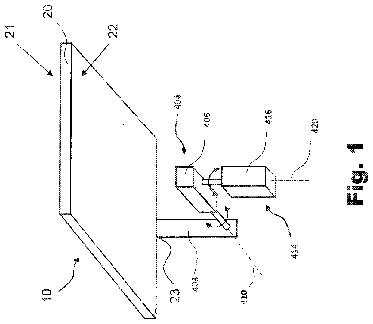
[0042]FIG. 1 is a schematic perspective view from below of a mechanism for directing a solar panel according to an embodiment of the invention. The solar panel assembly 10 comprises a platform 20. On the upper surface 21 of the platform 20, a photovoltaic, i.e. solar panel (not shown) as well as optional sensors of a tracking device are mounted. In an alternative embodiment, the platform 20 itself can comprise a solar cell module with a corresponding perimeter frame. In either case, the upper surface 21 of the platform 20 is to be oriented to the sky and provides the solar panel surface, whereas the underside 22 comprises one or more attachment points 23 for the adjustment, i.e. directional, mechanisms ...


PUM


Abstract

A solar panel assembly (10) having a stand (30), a solar panel platform (20, 120) and one or more directional mechanisms (40; 404, 414) connecting the stand (30) with the solar panel platform. One or more optical elements (50; 161, 162) are provided at all or portions of the edges (24) of the platform around the solar panel directing the light under the platform (20, 120) or towards its underside (22), and then to the ground (31) under or near the solar panel assembly. One or more of the optical elements (161, 162) are mounted on an inner side of a profile (160). The profile (160) is connected via a web (164) to the solar panel platform (120) and the web is connected with a drive within the platform. The connection of the web extends the profile from the platform creating a passage (124) between the profile and the platform.

Description

TECHNICAL FIELD[0001]The present invention relates to a directional solar panel assembly according to the preamble of claim 1.PRIOR ART[0002]WO 2016 / 074342 discloses a horizontal single-axis solar tracker support stand and a linkage system thereof, comprising a vertical column, a main beam that is rotatable and is provided on the vertical column, and a support frame fixed to the main beam and able to rotate with the main beam. The fixed support frame horizontally extends in a north-south orientation and is provided with a solar cell assembly arranged so as to form an inclined angle relative to a horizontal plane. When used in the northern hemisphere, the solar cell assembly is arranged at an inclined angle such that its northern side is higher than its southern side; the opposite angle of inclination is used in the southern hemisphere.[0003]This type of installation aims at providing lines of solar cell assemblies being orientable in an efficient way following the sun. It solves a p...

Claims


Application Information

Patent Timeline
Patent Type & Authority Applications(United States)
IPC IPC(8): F24S30/452A01G9/24H02S20/10H02S40/22H02S20/32
CPCH02S40/22F24S30/452H02S20/32A01G9/243H02S20/10F24S23/12Y02E10/47Y02E10/52Y02A40/25Y02P60/12A01G9/249Y02E10/50
Inventor SAEED, OSMAN
Owner ELEMENTAL ENG
Why Eureka
Try Eureka