Method of modifying a surface of a sample, and a scanning probe microscopy system

a scanning probe and microscopy technology, applied in scanning probe microscopy, measuring devices, instruments, etc., can solve the problems of complex system, multiple scanning and cantilevers, typical nano-scratching, etc., to achieve the effect of reducing the distance between the probe and the sample surface, increasing or decreasing the force, and improving accuracy

Inactive Publication Date: 2019-11-21
NEDERLANDSE ORG VOOR TOEGEPAST-NATUURWETENSCHAPPELIJK ONDERZOEK (TNO)
View PDF0 Cites 3 Cited by
  • Summary
  • Abstract
  • Description
  • Claims
  • Application Information

AI Technical Summary

Benefits of technology

[0033]Optionally, the excitation signal results in a probe tip deflection amplitude, wherein the probe actuated with an excitation signal at a first excitation frequency results in a first probe tip deflection amplitude, and the probe actuated with an excitation signal at a second excitation frequency results in a second probe tip deflection amplitude, wherein the first excitation frequency and second excitation frequency are configured so that the first probe tip deflection amplitude substantially corresponds to the second probe tip deflection amplitude. In this way, the probe tip deflection amplitudes can be kept constant, while the forces can be increased or decreased by changing a frequency of the excitation signal. In one embodiment, selectively adjusting the frequency of the excitation signal the force of the probe tip on the sample surface can be selectively adjusted while maintaining substantially a same probe tip deflection amplitude. In this way, it is possible by changing a limited amount of input parameters, the force employed on the surface by the probe tip, while simultaneously preventing additional adjustment of the Z-level. Also, the method for modifying a surface a sample, e.g. for nano-patterning a sample, can be simplified. Note that the probe tip amplitude can be seen as a dynamic or periodic tip deflection which depends on the frequency response of probe. When the cantilever is vibrating in free air, the probe tip amplitude may correspond to a free-air amplitude.
[0034]Optionally, the resonance frequency tracking is performed for taking into account a change of a frequency response of the probe as a result of a change in the distance between the probe and the sample surface by which a free air resonance frequency of the probe is shifted to a shifted resonance frequency. The method can further comprise: determining the first probe tip deflection amplitude and the second probe tip deflection amplitude and a ratio n between the first probe tip deflection amplitude and the second probe tip deflection amplitude, and determining the shifted resonance frequency for which n times the first probe tip deflection amplitude substantially corresponds to the second probe tip deflection amplitude. A free air resonance frequency of the probe may shift to a shifted resonance frequency when

Problems solved by technology

One disadvantage of the scratching AFM method is that typically nano-scratching requires multiple times scanning and multiple cantilevers.

Method used


Image

  • Method of modifying a surface of a sample, and a scanning probe microscopy system
  • Method of modifying a surface of a sample, and a scanning probe microscopy system
  • Method of modifying a surface of a sample, and a scanning probe microscopy system

Examples


Embodiment Construction

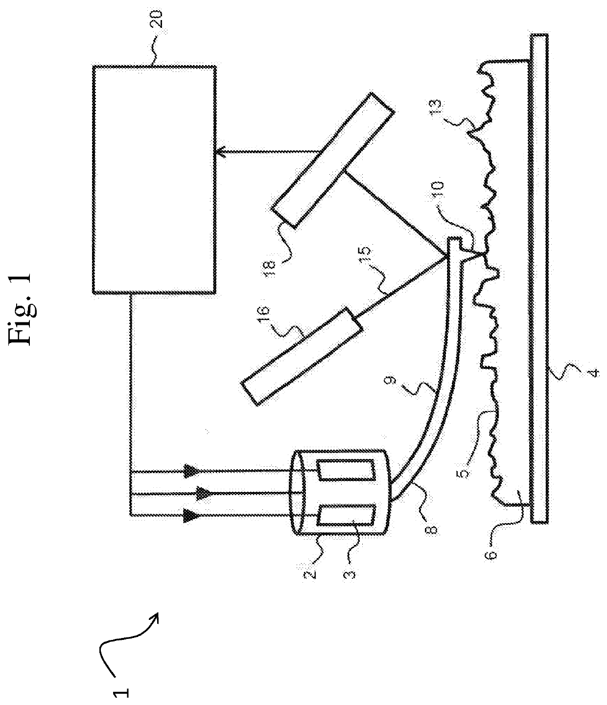
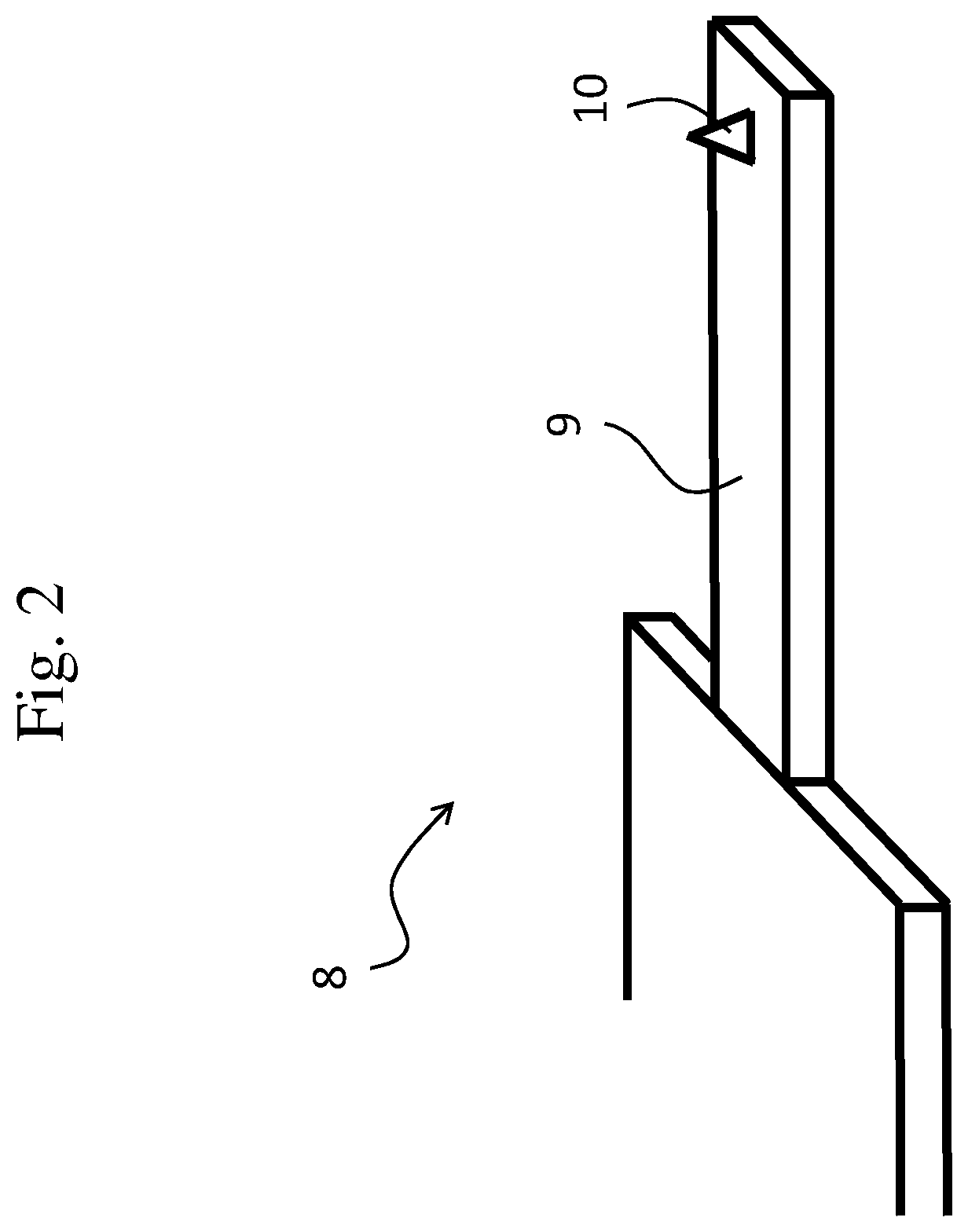
[0053]FIG. 1 schematically illustrates the working principle of a typical atomic force microscope (AFM). A probe head 2 is shown comprising piezo type drivers 3 for the X-, Y-, and Z-directional motion of a probe 8. The probe 8 comprises a cantilever 9 having a probe tip 10 arranged for scanning a sample surface 5 of a sample 6. During scanning, a dither piezo (not shown) or other means of actuations such as thermal, electrical, electrostatic, microwave, optical, photo-thermal, etc. actuation may drive the cantilever 9 in vibrational mode, advantageously close to a resonant frequency, to enable tapping of the probe tip 10 on the sample surface 5. The manner of applying a vibrational motion to the probe tip 10 is known to the skilled person.

[0054]Scanning of the sample surface 5 is performed by moving the probe tip 10 in the X- and Y direction parallel to the sample surface 5 (or alternatively, by moving the substrate surface in the X- and Y-directions while maintaining the position ...


PUM


Abstract

This document relates to a method and system for modifying a sample surface using a scanning probe microscopy system comprising a probe having a cantilever and a probe tip. The method comprises vibrating the probe; controlling a distance between the surface and the probe for tapping of the probe tip on the surface; and adjusting a tapping force of the probe tip on the surface during said tapping, so as to selectively modify the surface during the tapping. The probe is vibrated by employing a multi-frequency excitation comprising at least two frequencies for simultaneous imaging and modifying of the surface.

Description

FIELD OF THE INVENTION[0001]The present invention is directed at a method of modifying a surface of a sample using a scanning probe microscopy system, the system comprising a scan head including a probe, the probe comprising a cantilever and a probe tip arranged on the cantilever, wherein the scan head is movable relative to the sample for scanning the sample surface with the probe tip, the method comprising the steps of: vibrating the probe using an actuator for excitation of the probe with an excitation signal; controlling a distance between the sample surface and the probe for tapping of the probe tip on the surface by said excitation of the probe; and adjusting a tapping force of the probe tip on the surface during said tapping, so as to selectively modify the surface during the tapping. The invention is further directed at a scanning probe microscopy system, and to a computer program product for a scanning probe microscopy system.BACKGROUND[0002]Scanning probe microscopy (SPM) ...

Claims


Application Information

Patent Timeline
IPC IPC(8): G01Q60/34G01Q80/00
CPCG01Q60/34G01Q20/00G01Q80/00
Inventor SADEGHIAN MARNANI, HAMEDKEYVANI JANBAHAN, ALIASGHARTAMER, MEHMET SELMANMATUROVA, KLARA
Owner NEDERLANDSE ORG VOOR TOEGEPAST-NATUURWETENSCHAPPELIJK ONDERZOEK (TNO)
Why Eureka
Try Eureka