Process for the synthesis of ammonia
- Summary
- Abstract
- Description
- Claims
- Application Information
AI Technical Summary
Benefits of technology
Problems solved by technology
Method used
Image

Examples
Embodiment Construction
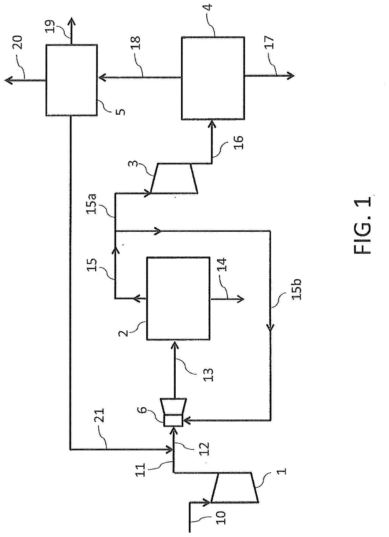
[0032]The plant of FIG. 1 essentially comprises a first compressor 1 elevating the pressure of a make-up gas from the front-end pressure to a first pressure P1, a first ammonia synthesis loop 2, a second compressor 3 elevating the pressure of the effluent of the first loop 2 to a second pressure P2, a second ammonia synthesis loop 4, a purge gas recovery section 5 and an ejector 6. The first loop 2 operates at pressure P1 and the second loop 4 operates at pressure P2.
[0033]Said first pressure P1 is preferably in the range 60-130 bar and said second pressure P2 is preferably in the range 150-280 bar.
[0034]A make-up gas 10 is compressed in the first compressor 1 to the pressure P1. Said make-up gas 10 is obtained in a front-end section (not shown) of the plant, for example by reforming of a hydrocarbon feedstock at a pressure which is significantly lower than pressure P1, e.g. of around 15 to 30 bar.
[0035]The so compressed make-up gas 11 is mixed with a hydrogen-containing stream 21 e...
PUM
 Abstract
Description
Claims
Application Information
 - R&D
- Intellectual Property
- Life Sciences
- Materials
- Tech Scout
- Unparalleled Data Quality
- Higher Quality Content
- 60% Fewer Hallucinations
Browse by: Latest US Patents, China's latest patents, Technical Efficacy Thesaurus, Application Domain, Technology Topic, Popular Technical Reports.
© 2025 PatSnap. All rights reserved.Legal|Privacy policy|Modern Slavery Act Transparency Statement|Sitemap|About US| Contact US: help@patsnap.com