

Speaker Cone and a Speaker Having the Same
- Summary
- Abstract
- Description
- Claims
- Application Information
AI Technical Summary
Benefits of technology
Problems solved by technology
Method used
Image

Examples
Embodiment Construction
[0025]The aforementioned and other objectives and advantages of this disclosure will become clearer in light of the following detailed description of an illustrative embodiment of this invention described in connection with the drawings.
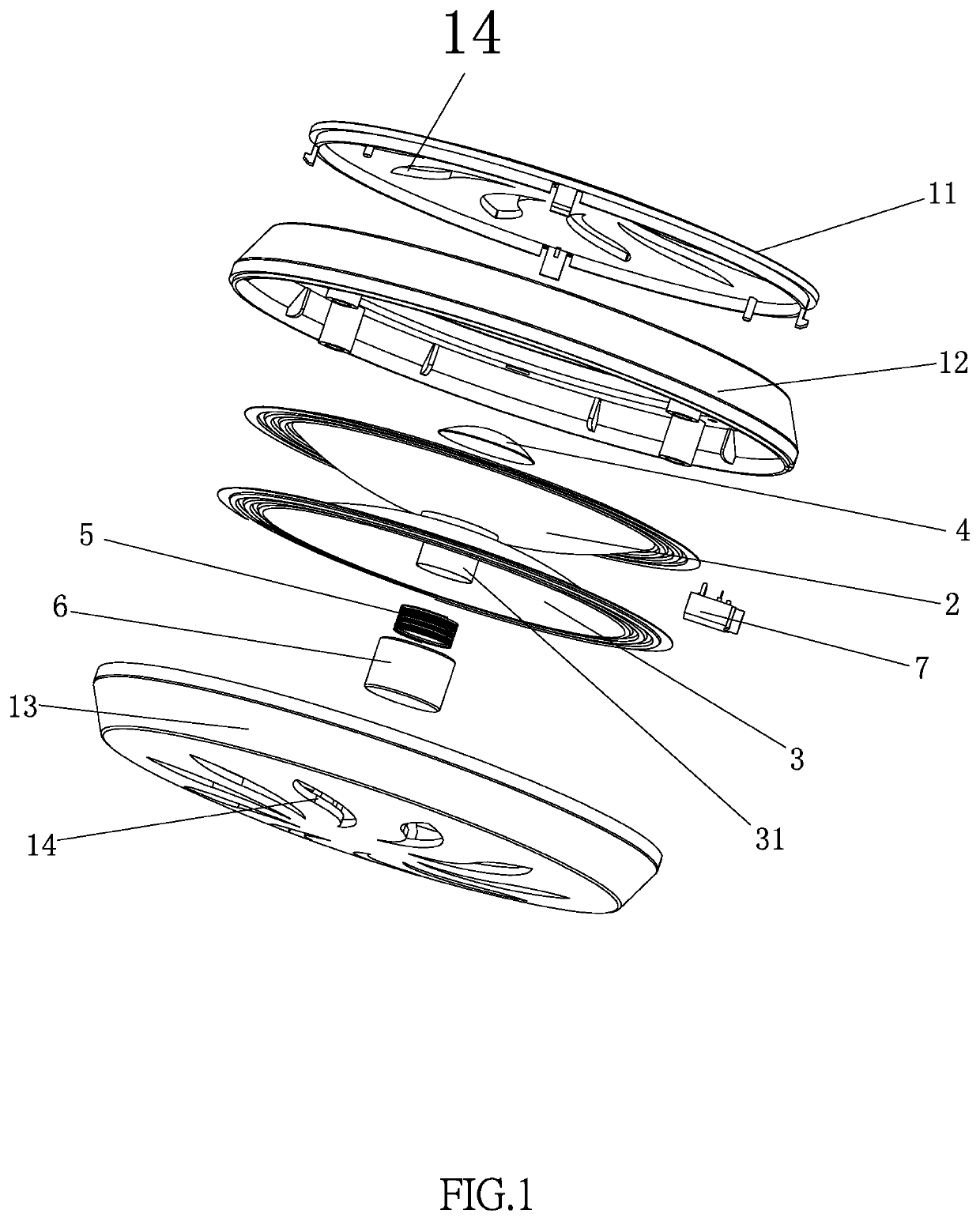
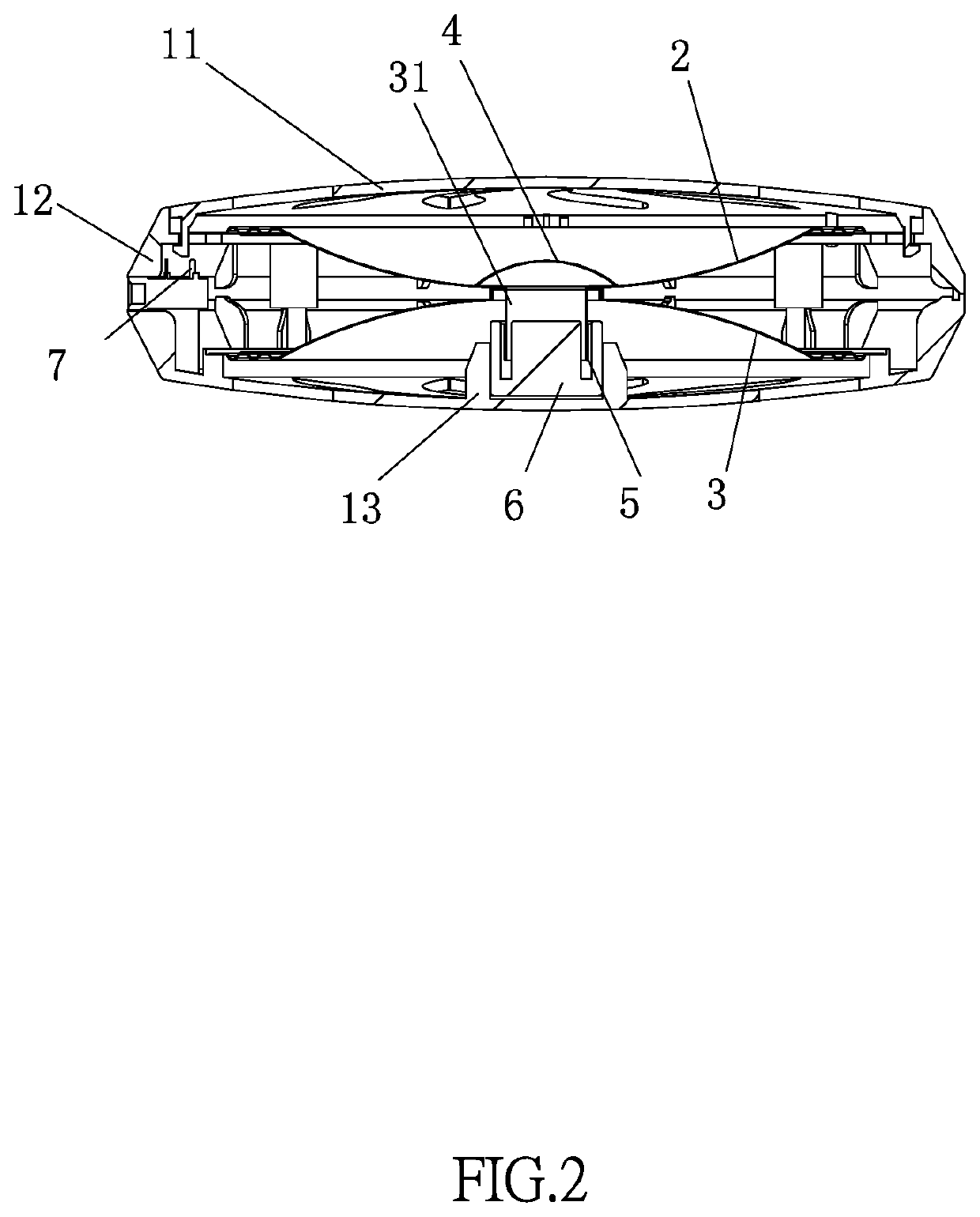
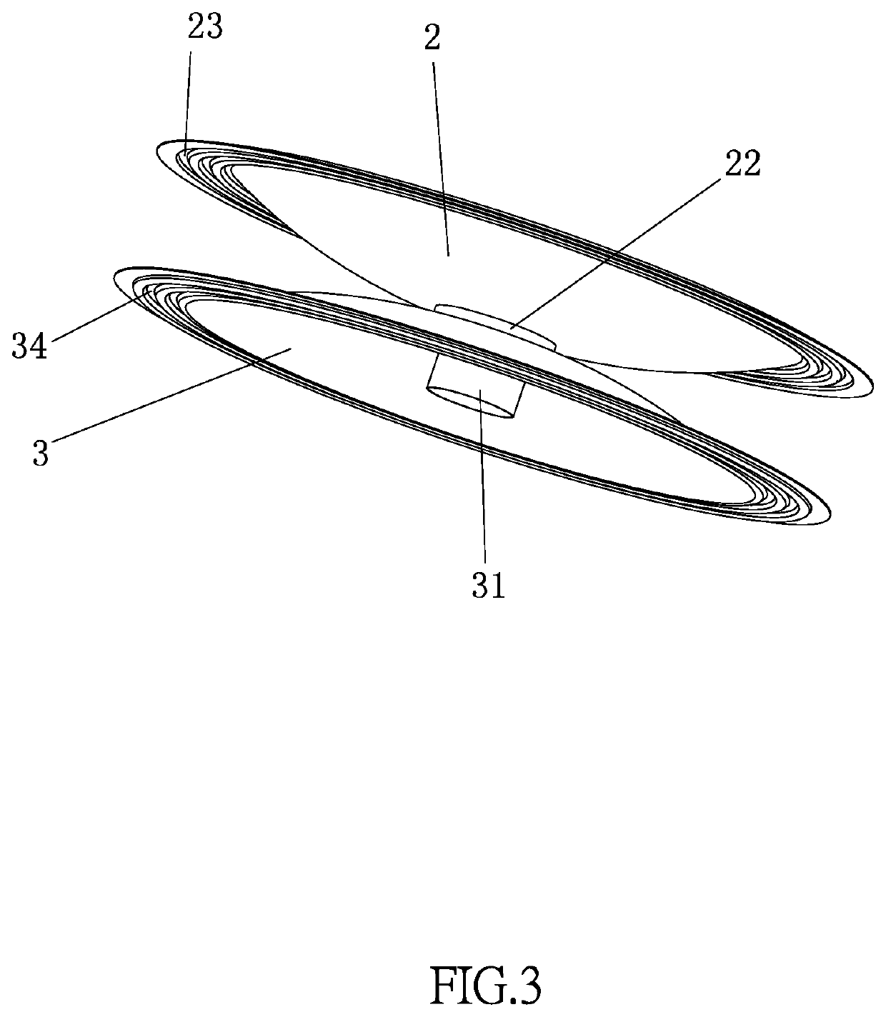
[0026]An explicit embodiment of the disclosed speaker is shown in FIGS. 1 to 6. The speaker includes a speaker cone assembly, a housing, a sound coil 5, a ring magnet 6, an audio device 7 and a dust cover 4. More explicitly, the housing includes from top to bottom an upper cover 11, a middle cover 12, and a lower cover 13 connected in a detachable way. In this embodiment, for the convenience of mass production and maintenance and tests of the speaker, the detachable connection among the upper cover 11, the middle cover 12, and the lower cover 13 in the form of an engagement connection. Of course, the detachable connection can also be achieved using screws. The connection method can be determined according to practical needs. To ensure good appearance...
PUM
 Abstract
Description
Claims
Application Information