Method for machining of ball tracks of inner races of constant velocity joints

a technology of constant velocity joints and machining methods, which is applied in the direction of manufacturing tools, gear teeth, mechanical equipment, etc., can solve the problems of increasing the complexity of the milling operation and the manufacturing time required to perform the multi-stage milling operation, complex machines specifically designed, and the efficiency of such processes tends to be less than desired, so as to reduce the machining time

Inactive Publication Date: 2019-12-05
SANDVIK INTELLECTUAL PROPERTY AB
View PDF0 Cites 8 Cited by
  • Summary
  • Abstract
  • Description
  • Claims
  • Application Information

AI Technical Summary

Benefits of technology

[0008]Accordingly, it is an object of the present invention to provide an improved method for machining of ball tracks of inner races of constant velocity joints. In particular, it is an object to provide such an improved method adapted to reduce the machining time required as compared to the prior art. These objects are achieved by a method as defined in independent claim 1, a cutting insert adapted to be replaceably arranged along a periphery of a tool body of a power skiving cutting tool for machining of ball tracks of inner races of constant velocity joints as defined in independent claim 6 and a power skiving cutting tool for machining of ball tracks of inner races of constant velocity joints as defined in independent claim 12. Preferred embodiments are defined in the dependent claims.

Problems solved by technology

Accordingly, the use of such multi-stage machining approaches adds considerably to the complexity of the milling operation and also to manufacturing time required to perform the multi-stage milling operation.
Especially with regards to producing the inner race for the balls, in many cases complex machines specifically designed for this purpose are used.
Apart from the complexity and costs added using such special purpose machines, the efficiency of such processes tend to be less than desired.

Method used


Image

  • Method for machining of ball tracks of inner races of constant velocity joints
  • Method for machining of ball tracks of inner races of constant velocity joints
  • Method for machining of ball tracks of inner races of constant velocity joints

Examples


Embodiment Construction

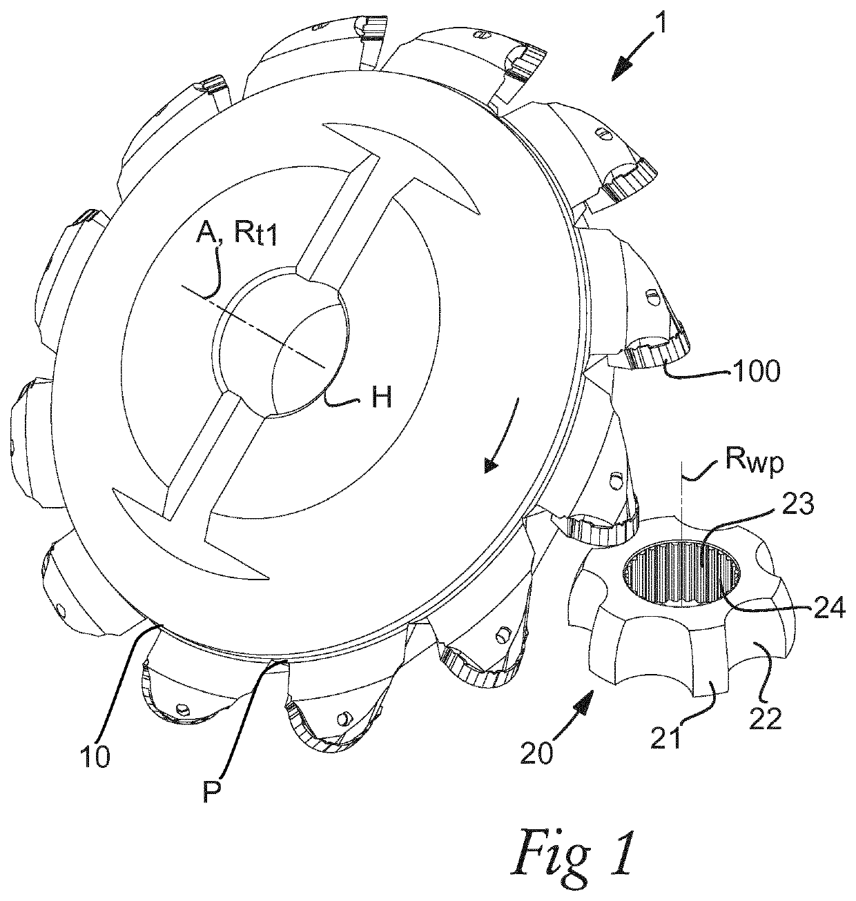
[0066]A power skiving tool 1 according to one exemplary embodiment is shown in a perspective view along with an exemplary workpiece 2. The tool 1 comprises a tool body 10 which may be described as ring, or disc-shaped, extending along an axial direction A, coinciding with the axis of rotation Rt1 of the tool, and along a radial direction R. A plurality of cutting members in the form of replaceable inserts 100 are arranged equally spaced along a periphery P of the tool body.

[0067]The illustrated tool body 10 is a steel body and is adapted to be attached the tool to a spindle providing a rotational movement to the tool, by means of an engagement by means of the center hole H.

[0068]The outer diameter of the tool body of the illustrated embodiment, i.e. the diameter at the periphery of the tool body, is approximately 150 mm. Further, the illustrated exemplary embodiment of FIG. 1 comprises twelve cutting inserts 100 arranged along the periphery of the tool body, the design of which will...


PUM

PropertyMeasurementUnit
anglesaaaaaaaaaa
length extensionaaaaaaaaaa
angleaaaaaaaaaa

Abstract

A method for machining of ball tracks of an inner race of a constant velocity joint includes the step of providing a power skiving tool having a plurality of cutting members and a first axis of rotation and providing a work piece having an outer envelope surface extending along an axis of rotation. The first axis of rotation of the power skiving tool is arranged at a first distance from the axis of rotation of the work piece and oriented at a first angle. A first rotational speed to the power skiving tool and a second rotational speed to the work piece and a relative movement between the work piece and the power skiving tool, is applied such that the cutting members engage the outer envelope surface to machine the ball tracks. A cutting insert and a power skiving cutting tool are also provided.

Description

FIELD OF THE INVENTION[0001]The present invention generally relates to the field of machining of constant velocity joints. In particular, the present invention relates to machining of ball tracks of inner races of constant velocity joints.TECHNICAL BACKGROUND[0002]Constant velocity joints are joints transmitting a rotational movement from an input shaft to an output shaft at constant rotational velocity more or less regardless of the angle between the input- and output shaft. Such joints may provide such a functionality by means of for example an inner and an outer housing having a number of balls arranged in races there between. The races may be split into an inner race and an outer race respectively arranged in the inner and outer housing, such that the inner and outer housing, being attached to the input- and output shaft respectively, may rotate about their respective axis of rotation while assuming an angle with respect to one another.[0003]Such a ball and race design put high ...

Claims


Application Information

Patent Timeline
Patent Type & Authority Applications(United States)
IPC IPC(8): B23F5/16B23C3/30B23C3/32B23C5/08B23C5/14B23C5/22B23Q27/00
CPCB23C2200/0416B23Q27/006B23F5/163B23C3/30B23C5/2221B23C3/32B23C5/08B23C5/14B23D15/14B23C5/2213
Inventor SJOO, STUREHUPFER, RENE
Owner SANDVIK INTELLECTUAL PROPERTY AB
Why Eureka
Try Eureka