
Rotary electric machine member manufacturing method

Pending Publication Date: 2019-12-05
AISIN CORP
View PDF0 Cites 0 Cited by
  • Summary
  • Abstract
  • Description
  • Claims
  • Application Information

AI Technical Summary

Benefits of technology

The present invention is a method for making a rotary electric machine member that reduces the likelihood of cracks forming in welds due to welding-related tension.

Problems solved by technology

The resulting tensile stress may thus cause the welds to develop cracks extending along stacking surfaces of the electromagnetic steel sheets.
A welding method that involves performing deep penetration welding with small energy (in particular, laser welding that involves making a keyhole so as to provide a molten pool and solidifying the molten pool) may induce occurrence of noticeable cracks because the time required from melting to solidification is short.

Method used


Image

  • Rotary electric machine member manufacturing method
  • Rotary electric machine member manufacturing method
  • Rotary electric machine member manufacturing method

Examples


first embodiment

Structure of Rotary Electric Machine

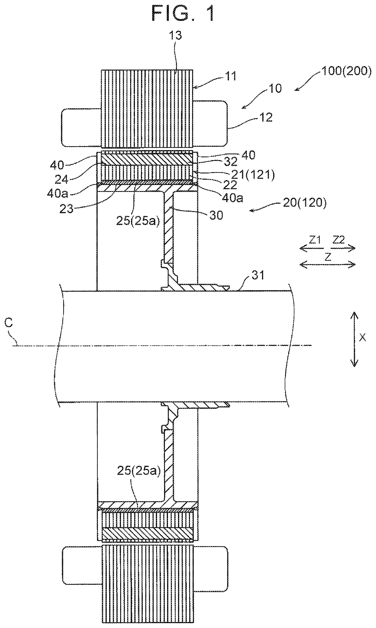
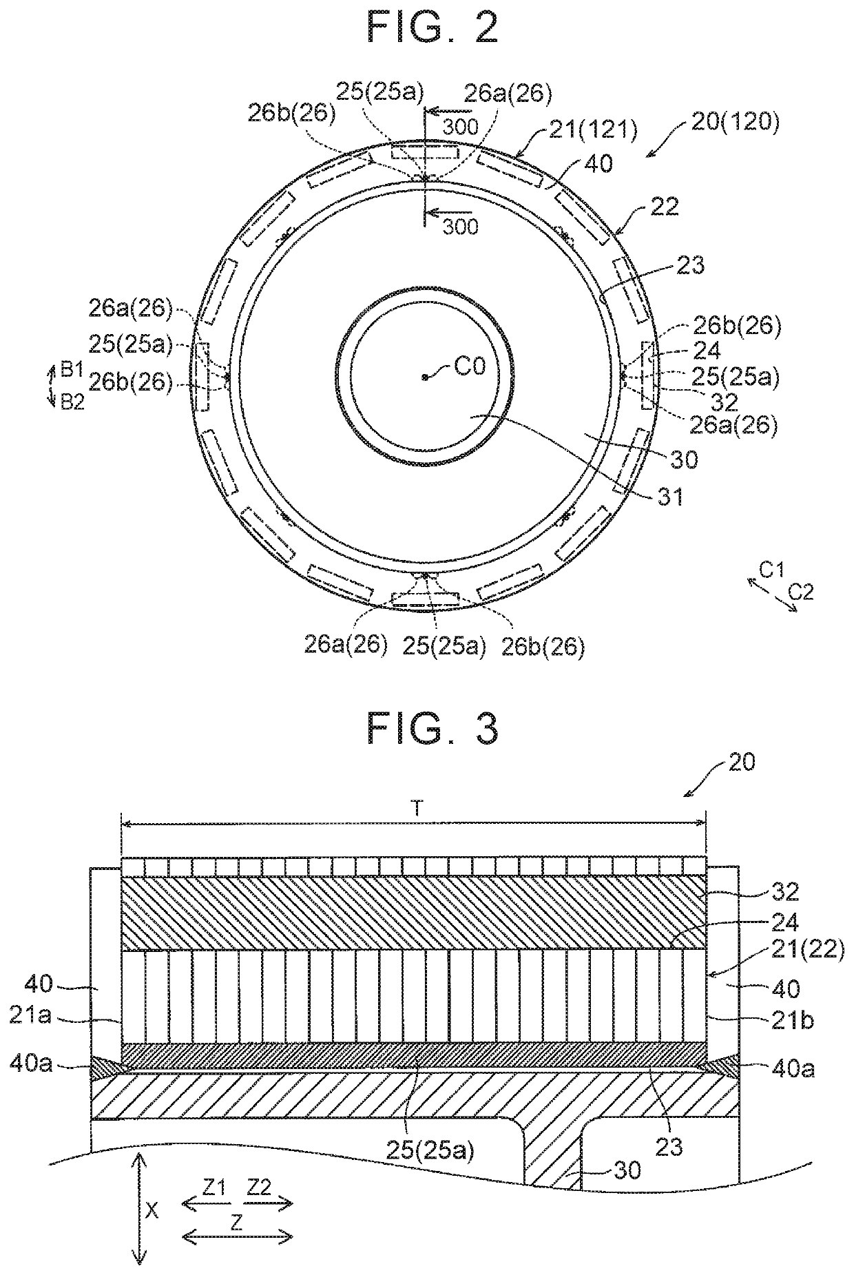
[0025]A structure of a rotary electric machine 100 (a rotor 20) according to a first embodiment will be described with reference to FIGS. 1 to 4.

[0026]As used herein, the term “rotation axis direction” refers to a direction extending along a rotation axis C of the rotor 20 (a rotor core 21) when the rotor 20 is in a completed state. The direction extending along the rotation axis C corresponds to a direction Z (see FIG. 1). As used herein, the term “peripheral direction” refers to a peripheral direction of the rotor 20 (the rotor core 21) when the rotor 20 is in the completed state. The peripheral direction of the rotor 20 corresponds to a direction B1 or a direction B2 (see FIG. 2). As used herein, the term “radially inward” refers to a direction radially toward a rotation center C0 of the rotor 20 (the rotor core 21) when the rotor 20 is in the completed state. The direction radially toward the rotation center C0 corresponds to, for example, a d...

second embodiment

[0048]A second embodiment will be described below with reference to FIGS. 8 and 9. In the second embodiment, a rotor core of a rotor in a completed state has gaps between adjacent ones of electromagnetic steel sheets unlike the first embodiment.

[0049]A rotary electric machine 200 according to the second embodiment of the present application differs from the rotary electric machine 100 according to the first embodiment in that the rotary electric machine 200 includes a rotor 120. As illustrated in FIG. 8, the rotor 120 according to the second embodiment of the present application differs from the rotor 20 according to the first embodiment in that the rotor 120 includes a rotor core 121.

[0050]In the second embodiment, the thickness T of the rotor core 121 is larger than the minimum thickness. Specifically, the rotor core 121 according to the second embodiment has the gaps D between adjacent ones of the electromagnetic steel sheets 22 as illustrated in FIG. 8, with the rotor 120 in the...


PUM

PropertyMeasurementUnit
Lengthaaaaaaaaaa
Thicknessaaaaaaaaaa
Densityaaaaaaaaaa

Abstract

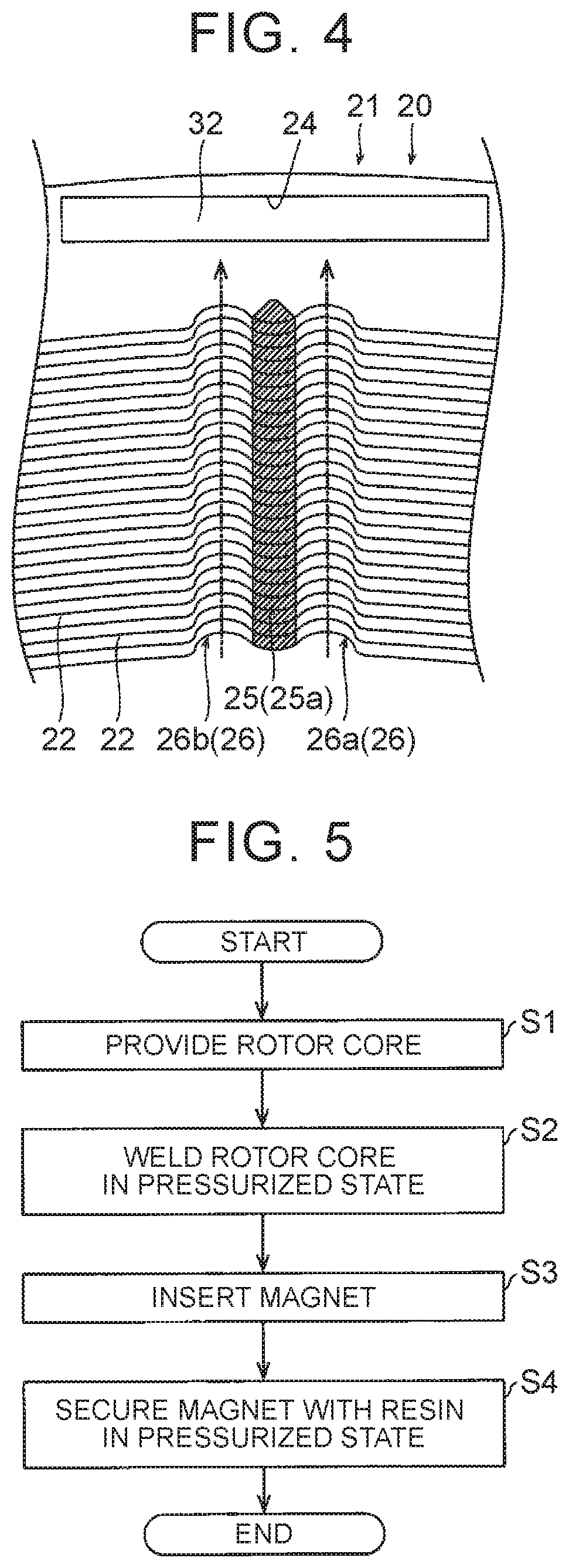
A rotary electric machine member manufacturing method includes: a step of providing a motor core by stacking a plurality of electromagnetic steel sheets; and a step of welding the motor core by keyhole welding while pressurizing the motor core in a stacking direction with a welding pressure lower than that at which the thickness of the motor core in the stacking direction levels off. The thickness is a length of the motor core between a first end of the motor core and a second end of the motor core.

Description

CROSS REFERENCE TO RELATED APPLICATIONS[0001]This application is a National Stage of International Application No. PCT / JP2018 / 009353 filed Mar. 9, 2018, claiming priority based on Japanese Patent Application No. 2017-045337 Filed Mar. 9, 2017.TECHNICAL FIELD[0002]Aspects of the present application relate to rotary electric machine member manufacturing methods.BACKGROUND ART[0003]A rotary electric machine member manufacturing method including a step of welding a motor core is known in the related art. Such a rotary electric machine member manufacturing method is disclosed in, for example, Japanese Patent Application Publication No. 2016-103882 (JP 2016-103882 A).[0004]JP 2016-103882 A discloses a rotor (rotary electric machine member) manufacturing method including a step of providing a rotor core (motor core) by stacking a plurality of electromagnetic steel sheets, and a step of welding an inner peripheral surface of the rotor core in a rotation axis direction of a rotor.RELATED ART...

Claims


Application Information

Patent Timeline
IPC IPC(8): H02K15/03H02K1/27B23K26/28
CPCB23K26/28H02K15/03H02K1/276B23K2103/02B23K2101/36B23K26/24B23K2101/38Y10T29/49012
Inventor USHIDA, HIDEHARUMATSUBARA, TETSUYAANAI, TAKEHIRO
Owner AISIN CORP
Learn More