
Pulse laser device, transparent member welding method and transparent member welding apparatus

Inactive Publication Date: 2013-01-10
AISIN SEIKI KK
View PDF3 Cites 17 Cited by
  • Summary
  • Abstract
  • Description
  • Claims
  • Application Information

AI Technical Summary

Benefits of technology

The patent describes a method for welding transparent materials using a long pulse laser and a coating of absorbing material. This method is complicated and increases welding costs. A modification process using ultra-short pulse lasers and heat accumulation effects are also described, which can weld transparent materials without causing cracks or reducing them.

Problems solved by technology

Although, until now, a transparent material such as glass has been able to be cut utilizing multiphoton absorption caused by a high-peak power ultra-short pulse laser, it is difficult to perform satisfactory welding that causes no crack and has a high welding strength.
When a high-peak power ultra-short pulse laser is irradiated to the interface of a transparent body materials, if even a slight gap (200 nm or less) is present in the interface, a crack is produced in the interface or the abrasion of the interface only occurs and welding is not achieved.
It is therefore impractical to put, to practical use, welding using only a high-peak power ultra-short pulse laser.
Hence, the energy or the fluence of a laser that can be irradiated is limited.
For example, if the energy or the fluence of a laser is increased beyond necessity in order to increase the bead width of welding, a crack is produced to lower the welding strength.
In other words, since the long pulse laser is absorbed not only by the interface but also by the surface or the entire material, it is impossible to weld the transparent body material only with the long pulse laser.
However, this method is complicated, and causes the welding cost to be increased.

Method used


Image

  • Pulse laser device, transparent member welding method and transparent member welding apparatus
  • Pulse laser device, transparent member welding method and transparent member welding apparatus
  • Pulse laser device, transparent member welding method and transparent member welding apparatus

Examples


first embodiment

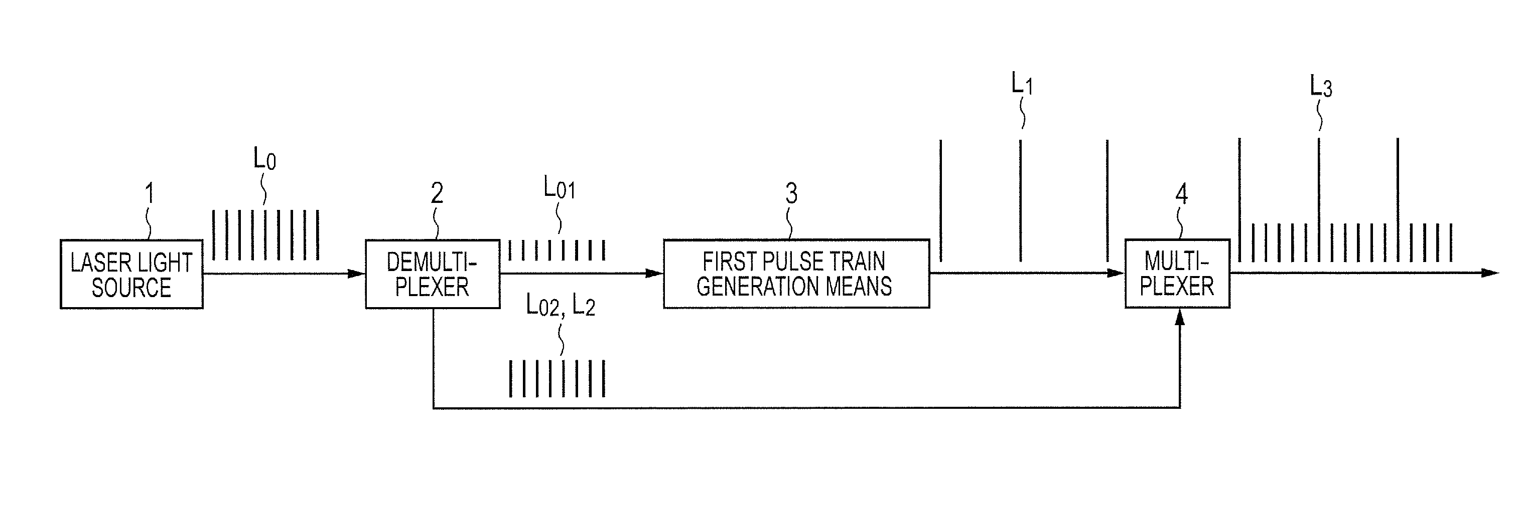
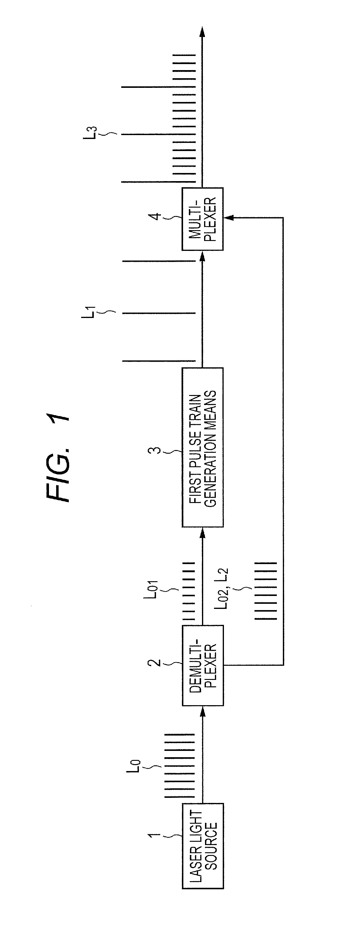
[0056]As shown in FIG. 1, the pulse laser device of the present embodiment includes: a laser light source 1 that outputs a repeated short pulse laser (seed pulse train) L0; a demultiplexer 2 that demultiplexes the seed pulse train L0 output from the laser light source 1 into two short pulse lasers (first seed pulse train L01, second seed pulse train L02); first pulse train generation means 3 that changes the repeated frequency and the peak power of the first seed pulse train L01 demultiplexed by the demultiplexer 2 to generate a first pulse train L1; and a multiplexer 4 that multiplexes the second seed pulse train L02 demultiplexed by the demultiplexer 2 and the first pulse train L1 generated by the first pulse train generation means 3.

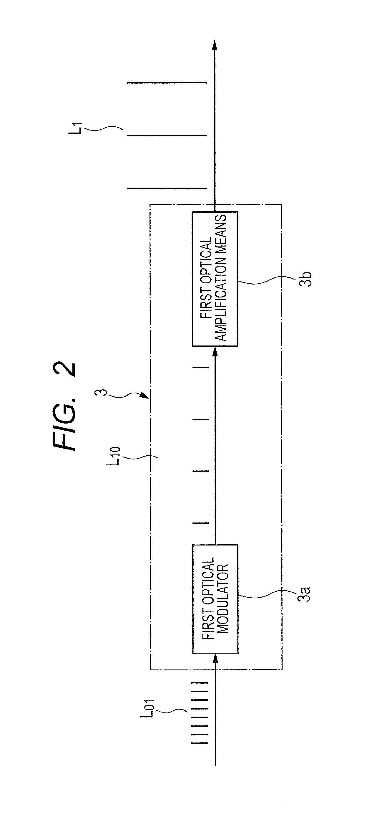
[0057]As shown in FIG. 2, the first pulse train generation means 3 includes: a first optical modulator 3a that changes the repeated frequency f0 of the first seed pulse train L01 into a frequency f1 which is lower than f0; and first optical amplificat...

second embodiment

[0090]As shown in FIG. 5, the pulse laser device of the present embodiment greatly differs from the pulse laser device of the first embodiment in that second pulse train generation means 5 parallel to the first pulse train generation means 3 is provided between a demultiplexer 2A and the multiplexer 4.

[0091]As shown in FIG. 6, the second pulse train generation means 5 includes: a second optical modulator 5a that changes the repeated frequency f0 of the second seed pulse train L02 into a frequency f2 which is lower than f0; and second optical amplification means 5b that amplifies the peak power P02 of the second seed pulse train L02 to a peak power P2 which is greater than P02.

[0092]As the second optical modulator 5a, an acousto-optic (AOM), an electro-optic modulator (EOM), a magneto-optic modulator (MOM) or the like can be used.

[0093]The second optical amplification means 5b includes an optical amplifier. When the optical amplifier is a fiber amplifier, an expander that expands a p...

third embodiment

[0106]As shown in FIG. 7, the pulse laser device of the present embodiment greatly differs from the pulse laser device of the second embodiment in that chirp adjustment means 8 is provided after the multiplexer 4. The pulse laser device of the present embodiment is designed to produce the second pulse train having a time width longer than the first pulse train of the second embodiment.

[0107]The first pulse train generation means 3 includes: the first optical modulator 3a that changes the repeated frequency f0 of the first seed pulse train L01 into the frequency fl which is lower than f0; and the first optical amplification means 3b that amplifies the peak power P01 of the first seed pulse train L01 to the peak power P1 which is greater than P01.

[0108]The first optical amplification means 3b includes an expander 31b and an amplifier 32b.

[0109]The second pulse train generation means 5b includes: the second optical modulator 5a that changes the repeated frequency f0 of the second seed...


PUM

PropertyMeasurementUnit
Frequencyaaaaaaaaaa
Poweraaaaaaaaaa
Widthaaaaaaaaaa

Abstract

An inexpensive pulse laser device that outputs a laser pulse capable of welding a transparent member is provided. There is provided a pulse laser device including: a laser light source 1 that outputs a repeated pulse laser; a demultiplexer 2 that demultiplexes the pulse laser output from the laser light source 1 into two pulse lasers; first pulse train generation means 3 that generates a first pulse train by changing at least a peak power and / or a pulse width of one of the two pulse lasers demultiplexed by the demultiplexer 2; and a multiplexer 4 that multiplexes the other of the two pulse lasers demultiplexed by the demultiplexer 2 and the first pulse train generated by the first pulse train generation means 3, in which a pulse laser in which a low-peak power pulse laser is superimposed on a high-peak power ultra-short pulse laser is output.

Description

TECHNICAL FIELD[0001]The present invention relates to a laser device that outputs a high-peak power short pulse laser and a transparent member welding method and a transparent member welding apparatus using the laser device. More particularly, the present invention relates to a pulse laser device that outputs a pulse laser obtained by superimposing a repeated low-peak power pulse laser on a repeated high-peak power ultra-short pulse laser and a transparent member welding method and a transparent member welding apparatus using the laser device.BACKGROUND ART[0002]High power short pulse laser devices are practically important in various fields. In particular, a high-peak power ultra-short pulse laser having a high peak power is practically used for processing a transparent material and medical treatment in medicine and industry.[0003]The high-peak power ultra-short pulse laser device that has been practically used modulates a highly repeated frequency laser pulse train output from a m...

Claims


Application Information

Patent Timeline
IPC IPC(8): B23K26/00
CPCB23K26/0635B23K26/3266B23K26/324B23K26/0652B23K26/20C03B23/20B23K26/26B23K26/32B23K26/0624B23K26/244B23K2103/54B23K26/067B23K26/0622B23K26/21
Inventor OTA, MICHIHARU
Owner AISIN SEIKI KK
Learn More