
Second-order passive ring interferometer sensor and method

a passive ring interferometer and sensor technology, applied in the field of passive ring interferometers, can solve the problems of scale factor instability, limited accuracy of the gyroscope, and various limitations of the passive sagnac optical gyroscope that rely on first-order interference, and achieve the effect of increasing the true unambiguous dynamic rang

Active Publication Date: 2019-12-19
CHARLES STARK DRAPER LABORATORY
View PDF0 Cites 1 Cited by
  • Summary
  • Abstract
  • Description
  • Claims
  • Application Information

AI Technical Summary

Benefits of technology

The patent is about a device called a gyroscope that measures rotational velocity using laser light. The device uses a special technique called first-order interference, but it can experience interruptions during operation. When it is turned off or exposed to an environmental event that affects its signal, it may not accurately measure the amount of rotation that happened during that time. However, the device can use multiple wavelengths of light to determine the fringe order and increase the dynamic range of the measurements. This makes the device more reliable and accurate. The light source used in the device can be a laser or LED, and may include a conditioner to improve the quality of the light.

Problems solved by technology

Known passive Sagnac optical gyroscopes that rely on first-order interference suffer from various limitations.
One such limitation is scale factor instability.
Hence the accuracy of the gyroscope is limited by the accuracy by which λ of the light source is known, and instability of λ due to electronic drive fluctuations, environmental fluctuations, or component aging results in rotation measurement error.
As one example source of measurement error, external light sources that are based on superluminescent diodes (SLDs) are known to suffer from inherent centroid wavelength thermal sensitivity of typically +250 to +400 ppm / ° C., and integrated temperature stabilization is typically invoked to reduce the sensitivity of SLDs to external thermal fluctuations.
Other known external light sources, such as those based on rare-earth-doped superluminescent sources (REDSLSs), are also known to suffer from centroid wavelength thermal sensitivity due to environmental effects such as temperature fluctuations and exposure to ionizing radiation.
Another limitation of passive Sagnac optical gyroscopes that rely on first-order interference is the limited unambiguous dynamic range.
For applications where such a gyroscope is turned on while being in the unambiguous range and operating uninterrupted, it is known that it is possible to count the fringes that are passed and to keep a valid measurement over an extended dynamic range, but such fringe counting requires added complexity in the gyroscope electronics that becomes especially complex at high rotation rates due to the need for high-speed electronics.
Further, if such a gyroscope, reliant on first-order interference, experiences an interruption in operation for a period of time while it is rotating (for example if the gyroscope is turned off or if it experiences an environmental event that renders its Sagnac signal not representative of rotation), then, upon recovery from the interruption, it will suffer from ambiguity with respect to the amount of rotation that transpired during the period of time that the gyroscope was interrupted because of missing fringe counts.
However, such multi-wavelength detection also has the drawback of requiring added complexity.

Method used


Image

  • Second-order passive ring interferometer sensor and method
  • Second-order passive ring interferometer sensor and method
  • Second-order passive ring interferometer sensor and method

Examples


Embodiment Construction

[0051]A description of example embodiments of the invention follows. The following is a detailed description of the preferred embodiments of the invention, reference being made to the drawings in which the same reference numerals identify the same elements of structure in each of the several figures.

[0052]Figures shown and described herein are provided in order to illustrate key principles of operation and component relationships along their respective optical paths according to the present disclosure and are not drawn with intent to show actual size or scale. Some exaggeration may be necessary in order to emphasize basic structural relationships or principles of operations.

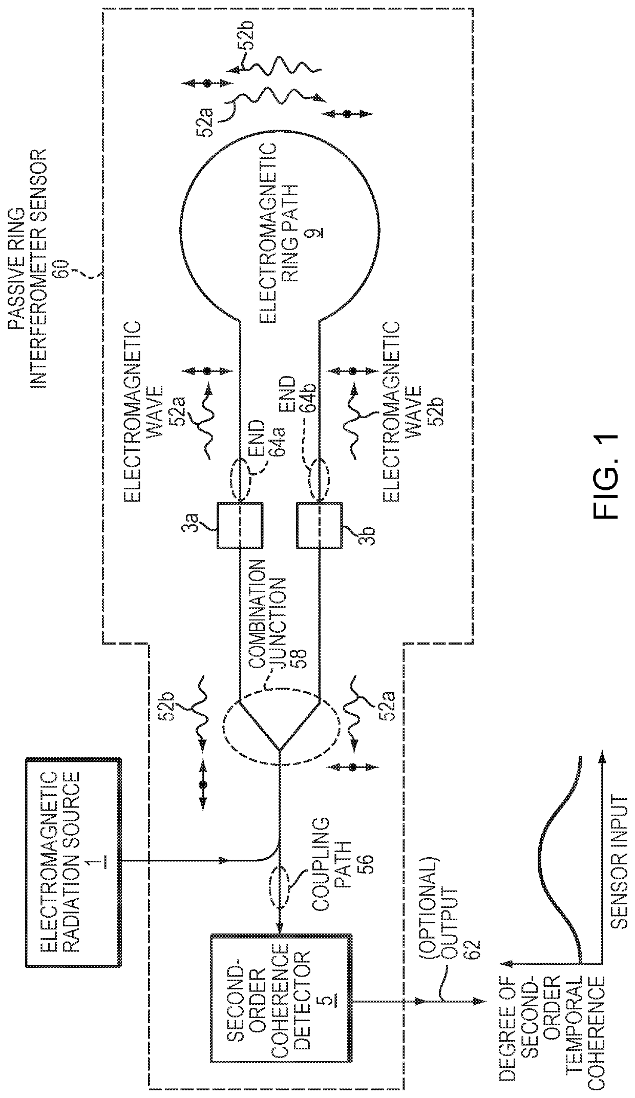
[0053]FIG. 1 is a schematic diagram illustrating an embodiment passive ring interferometer sensor 60 that functions by detecting second-order coherence. In particular, the sensor 60 includes an electromagnetic ring path 9 that is configured to receive a pair of electromagnetic waves 52a, 52b from an electromagnet...


PUM


Abstract

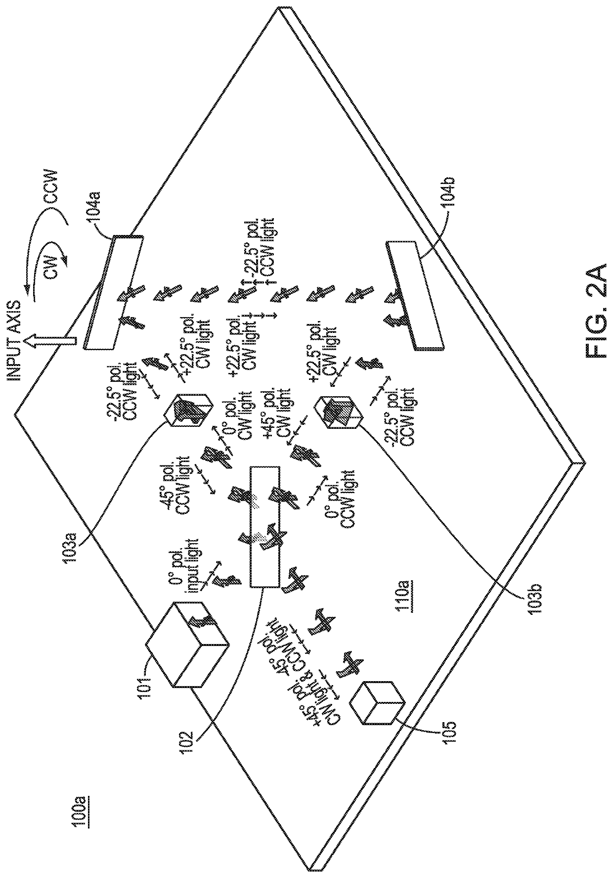
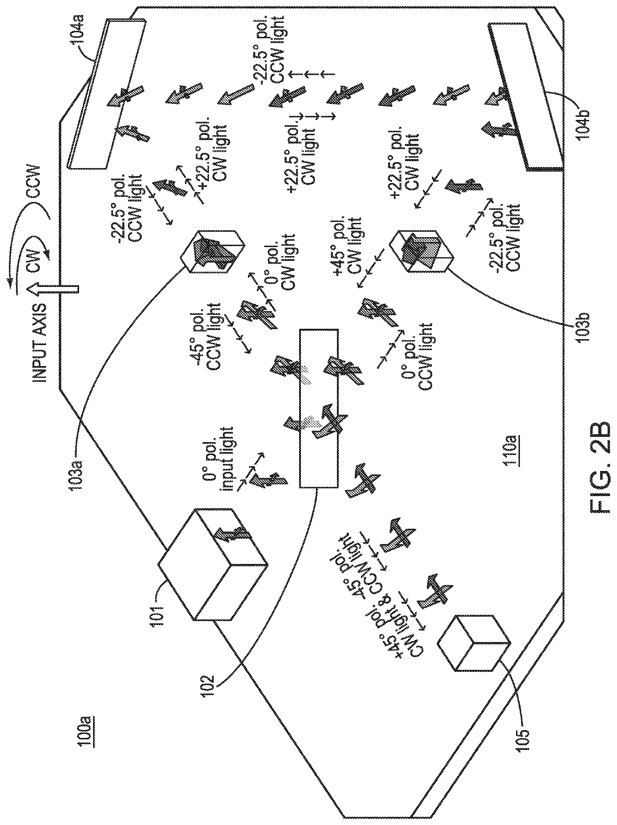
A passive ring interferometer sensor includes an electromagnetic ring path configured to receive a pair of electromagnetic waves from an electromagnetic radiation source and to direct the waves to be counter-propagating within the ring path toward respective ends of the path. A combination junction receives the waves from the respective ends and combines the waves to be co-propagating within a coupling path. Polarization elements are configured to set the waves to be mutually co-polarized within the electromagnetic ring path and to be mutually cross-polarized within the coupling path. A detector is configured to receive the mutually cross-polarized waves from the coupling path and to detect second-order coherence. Embodiments can sense rotation rate as fiber-optic gyroscopes or serve as other types of sensors such as gravitational wave sensors. Embodiments may have greatly increased unambiguous range and decreased sensitivity to any centroid wavelength shift.

Description

RELATED APPLICATIONS[0001]This application claims the benefit of U.S. Provisional Application No. 62 / 685,675, filed on Jun. 15, 2018. This application also claims the benefit of U.S. Provisional Application No. 62 / 775,308, filed on Dec. 4, 2018. The entire teachings of the above applications are incorporated herein by reference.GOVERNMENT SUPPORT[0002]This invention was made with government support under N00030-13-C-0007 from Department of Defense. The government has certain rights in the invention.FIELD[0003]This disclosure relates generally to passive ring interferometers that may be used in optical gyroscopes, and more particularly to a second-order passive ring interferometer that may form part of a Sagnac optical gyroscope, as well as a related method of passive ring interferometric sensing using second-order coherence.BACKGROUND[0004]Passive Sagnac optical gyroscopes are known, for example as described in G. Sagnac, C. R. Hebd. Seances Acad. Sci. 157, 708 (1913), and in H. C. ...

Claims


Application Information

Patent Timeline
IPC IPC(8): G01C19/72
CPCG01C19/727G01C19/721
Inventor FEKE, GILBERT D.
Owner CHARLES STARK DRAPER LABORATORY
Learn More