Check patentability & draft patents in minutes with Patsnap Eureka AI!

Applicator for die-cut parts and method for applying die-cut parts to surfaces, and a die-cut part strip

a technology for die-cut parts and parts, applied in the directions of mechanical equipment, transportation and packaging, other domestic objects, etc., can solve the problems of relatively large process footprint, large open-close process of bodywork parts, and relatively time-consuming process

Active Publication Date: 2020-01-02
TESA SE
View PDF2 Cites 0 Cited by
  • Summary
  • Abstract
  • Description
  • Claims
  • Application Information

AI Technical Summary

Benefits of technology

The present invention is aimed at providing an applicator and method for adhering die-cut parts to surfaces, with the aim of reducing disadvantages and improving efficiency. The applicator controls the propulsion of the die-cut part strip, allowing for precise positioning of subsequent die-cut parts on the surface. The method requires minimal space in the xy-plane and allows for quick positioning of die-cut parts on the surface, with the option of multiple positions being determined during the process. Overall, the invention simplifies the process of applying die-cut parts to surfaces.

Problems solved by technology

A frequent problem arising in the production of motor vehicles is that openings that have been made in bodywork parts have to be bonded closed again after processing operations.
Disadvantageously, this process is relatively time-consuming, since the robot arm has to be moved back to the die-cut part roll again after each bonding operation, in order to detach the next die-cut part from the die-cut part strip.
Disadvantageously, this process has a fairly large footprint, since the label dispenser has to be drawn over a certain distance by means of the robot arm.
This is disadvantageous, for example, in regions of an automotive panel that are difficult to access, as for example if the opening requiring closure is sited directly adjacent to a highly curved edge.

Method used


Image

  • Applicator for die-cut parts and method for applying die-cut parts to surfaces, and a die-cut part strip
  • Applicator for die-cut parts and method for applying die-cut parts to surfaces, and a die-cut part strip
  • Applicator for die-cut parts and method for applying die-cut parts to surfaces, and a die-cut part strip

Examples


Embodiment Construction

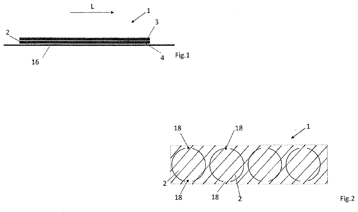
[0042]A die-cut part strip 1 shown in FIG. 1 has die-cut parts 2 which are arranged in a row and are spaced apart from one another. The spacing of the die-cut parts 2 from one another is guided by the particular application; it may be 1 mm, 2 mm, 3 mm to 6 mm, or 7 mm. All values in between are disclosed as well. The die-cut parts 2 are disposed along a longitudinal direction L in the die-cut part strip.

[0043]The die-cut part strip 1 comprises a carrier layer 3 and an adhesive layer 4. The carrier layer 3 consists of customary plastics; by way of example, but without limitation, mention may be made of the following:

[0044]polyethylene, polypropylene—especially the oriented polypropylene (OPP) generated by monoaxial or biaxial drawing, cyclic olefin copolymers (COC), polyvinyl chloride (PVC), polyesters—especially polyethylene terephthalate (PET) and polyethylene naphthalate (PEN), ethylene-vinyl alcohol (EVOH), polyvinylidene chloride (PVDC), polyvinylidene fluoride (PVDF), polyacryl...


PUM

PropertyMeasurementUnit
Forceaaaaaaaaaa
Adhesion strengthaaaaaaaaaa
Adhesivityaaaaaaaaaa

Abstract

The invention relates to an applicator for die-cut parts (2), having a die-cut part strip (1) with a longitudinal direction (L) having a carrier layer (3) and an adhesive layer (4), where an outer contour of the die-cut parts (2) is punched through the carrier layer and adhesive layer (3, 4) down to predetertnined breaking points (18) and a die-cut part complement (19) protrudes beyond the die-cut parts (2) continuously laterally to a longitudinal direction (L), and a punch head (8) over which the die-cut part strip (1) runs, where the die-cut parts (2) running over the punch head (8) face away from the punch head (8) by their adhesive layer (4), and the die-cut parts (2) can be pressed by means of the punch head (8) onto a surface (11).

Description

TECHNICAL FIELD[0001]The invention relates to an applicator for die-cut parts with a die-cut part strip having a carrier layer and an adhesive layer. The invention also relates to a method for applying die-cut parts to a surface. The invention also relates to a die-cut part strip having a carrier layer and an adhesive layer.BACKGROUND[0002]A frequent problem arising in the production of motor vehicles is that openings that have been made in bodywork parts have to be bonded closed again after processing operations. For example, bodywork parts may be surface-treated with liquid. The liquid needed for the surface treatment runs off automatically via openings made beforehand in the bodywork parts. Subsequently, the openings are closed again. Frequently, the openings are closed by hand, by taking die-cut parts from a die-cut part strip or a die-cut part sheet and adhering them by hand onto the openings. The die-cut parts have a carrier layer and an adhesive layer applied on one side of t...

Claims


Application Information

Patent Timeline
IPC IPC(8): B32B38/04B32B37/00B32B37/10B32B37/12B32B37/18B32B7/12
CPCB32B37/12B32B37/0046B32B37/1045B32B7/12B32B37/182B32B38/04B32B2519/00F16B11/00B65H35/0013B65H37/007B65H35/10B65H2301/5163B65H2301/51514B65H2801/51B65H2555/30B65H37/04B65H18/103B65H2301/5161B65H2553/80B65H2701/19B32B2605/08B32B2041/06Y10T156/107B29C66/9261B32B37/06Y10T156/1075Y10T156/1085
Inventor BRANDT, HANS-PETERSEIBERT, MATTHIAS
Owner TESA SE
Features
  • R&D
  • Intellectual Property
  • Life Sciences
  • Materials
  • Tech Scout
  • Unparalleled Data Quality
  • Higher Quality Content
  • 60% Fewer Hallucinations
Learn More