Bracket device and method

a technology of bracket devices and wires, applied in the direction of electrical cable installation, overhead installation, belts/chains/gearrings, etc., can solve the problems of difficult installation of some bracket devices, known bracket devices, and deficiencies, and achieve the effect of reducing the gap width

Active Publication Date: 2020-01-02
ALLIED BOLTS
View PDF23 Cites 8 Cited by
  • Summary
  • Abstract
  • Description
  • Claims
  • Application Information

AI Technical Summary

Benefits of technology

[0006]To achieve these and other advantages, and in accordance with the purpose of the disclosed subject matter, as embodied and broadly described, the disclosed subject matter includes a bracket device to secure a tail wire of a drop wire clamp to a structure. The bracket device generally includes a base having a surface. The bracket device further includes a retention hook having a first end, a second end, and a retention region defined between the first end and the second end. The first end of the retention hook is coupled to the base surface, and the second end of the retention hook is disposed at a predetermined distance from the base surface to define a gap therebetween having a width. The bracket device further includes a locking nut that is cooperatively coupled to the second end of the retention hook and adapted to move between an unlocked position to permit a wire to enter the retention region and a locked position in which a wire is retained by the retention hook in the retention region by a reduction of the gap width.
[0007]According to a further aspect of the disclosed subject matter, a method for securing a tail wire of a drop wire clamp to a structure with a bracket device as described above is provided. The method includes attaching the bracket device to a structure and cooperatively coupling a locking nut to the second end of the retention hook in an unlocked position. The method further includes inserting a wire having a gauge into the retention region with the locking nut in the unlocked position and then transitioning the locking nut from the unlocked position to the locked position. Transitioning the locking nut to the locked position retains the wire in the retention region since the width of the gap is less than the gauge of the wire when the locking nut is in the locked position.

Problems solved by technology

Some known bracket devices, however, have deficiencies.
This springing action of the wire can cause the wire to jump out of a bracket device that secured the wire to a structure.
Furthermore, installation of some bracket devices can be difficult.

Method used


Image

  • Bracket device and method
  • Bracket device and method
  • Bracket device and method

Examples


Embodiment Construction

[0019]Reference will now be made in detail to the various exemplary embodiments of the disclosed subject matter, exemplary embodiments of which are illustrated in the accompanying drawings. The structure and corresponding method of operation of the disclosed subject matter will be described in conjunction with the detailed description of the system.

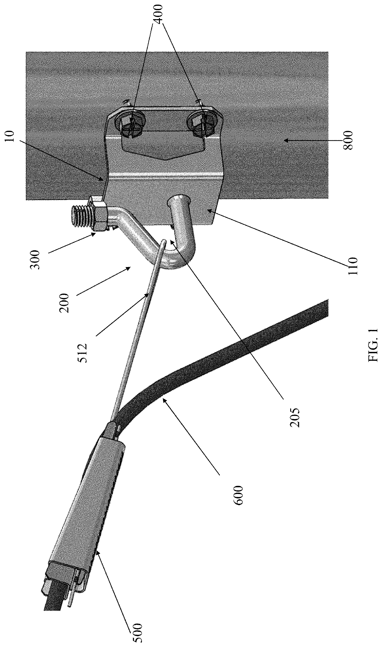
[0020]The apparatus and methods presented herein can be used for securing a wide variety of wires to a structure. The disclosed subject matter is particularly suited for securing utility wires, including fiber optic wires, to structures such as buildings. The securement can be at a point just short of the position in which the wire enters the building.

[0021]The bracket devices and methods for securing wires to structures of the disclosed subject matter have demonstrated desired performance characteristics not achieved by conventional bracket devices. For purpose of understanding, and not limitation, bracket devices of the disclosed subjec...


PUM


Abstract

A bracket device to secure a tail wire of a drop wire clamp to a structure including a base having a surface. The bracket device further includes a retention hook having a first end, a second end, and retention region defined between the first end and second end. The first end of the retention hook is coupled to the base surface, and the second end of the retention hook is disposed at a predetermined distance from the base surface to define a gap therebetween having a width. The bracket device further includes a locking nut that is cooperatively coupled to the second end of the retention hook and adapted to move between an unlocked position to permit a wire to enter the retention region and a locked position in which a wire is retained by the retention hook in the retention region by a reduction of the gap width.

Description

BACKGROUNDField of the Disclosed Subject Matter[0001]The presently disclosed subject matter relates generally to devices and methods to secure a wire to a structure.Description of the Related Art[0002]Bracket devices are commonly used in conjunction with drop wire clamps to secure telecommunication wires and the like to both round and flat structures. For example, such devices can be used to secure telephone cables, television cables, network cables, fiber optic cables, and the like to buildings, utility poles, or other structures. Often bracket devices are used to secure wires at an intermediate portion thereof to a point on a structure. For example, bracket devices are commonly used to secure a wire or wires to the outside of buildings at a point just short of the position in which the wires enter the building.[0003]Bracket devices to secure wires to structures are known in the art. Some bracket devices are designed to cooperate with clamps, such as drop wire clamps disclosed in U...

Claims


Application Information

Patent Timeline
Patent Type & Authority Applications(United States)
IPC IPC(8): F16G11/14F16M13/02
CPCF16M13/02F16G11/048F16G11/14H02G7/056
Inventor MALIN, GLEN K.
Owner ALLIED BOLTS
Why Eureka
Try Eureka