Supercharge Your Innovation With Domain-Expert AI Agents!

Compact radar switch/mimo array antenna with high azimuth and elevation angular resolution

a radar switch and array antenna technology, applied in the field of imaging radars, can solve the problems of limited radial velocities estimation, visual sensors also degraded, and limited light detection and ranging devices (lidars), and achieve the effect of increasing the effective aperture siz

Active Publication Date: 2020-01-02
ARBE ROBOTICS LTD
View PDF5 Cites 3 Cited by
  • Summary
  • Abstract
  • Description
  • Claims
  • Application Information

AI Technical Summary

Benefits of technology

The technical effects of this patent are not specified, but they may be identified by referring to the "objects and advantages" of the invention described in the text. As a senior R&D personnel, you should be able to understand the "technical effects" of this patent without adding any additional information.

Problems solved by technology

Visual sensors are also degraded by bad weather and poor visibility (e.g. fog, smoke, sand, storm etc.).
They are also limited in estimating radial velocities.
Light Detection And Ranging devices (LIDARs—used to measure distance to a target by illuminating that target with a laser light) are expensive, most have moving parts and very limited range.
This imposes a new set of requirements which modern radars does not comply with.

Method used


Image

  • Compact radar switch/mimo array antenna with high azimuth and elevation angular resolution
  • Compact radar switch/mimo array antenna with high azimuth and elevation angular resolution
  • Compact radar switch/mimo array antenna with high azimuth and elevation angular resolution

Examples


Embodiment Construction

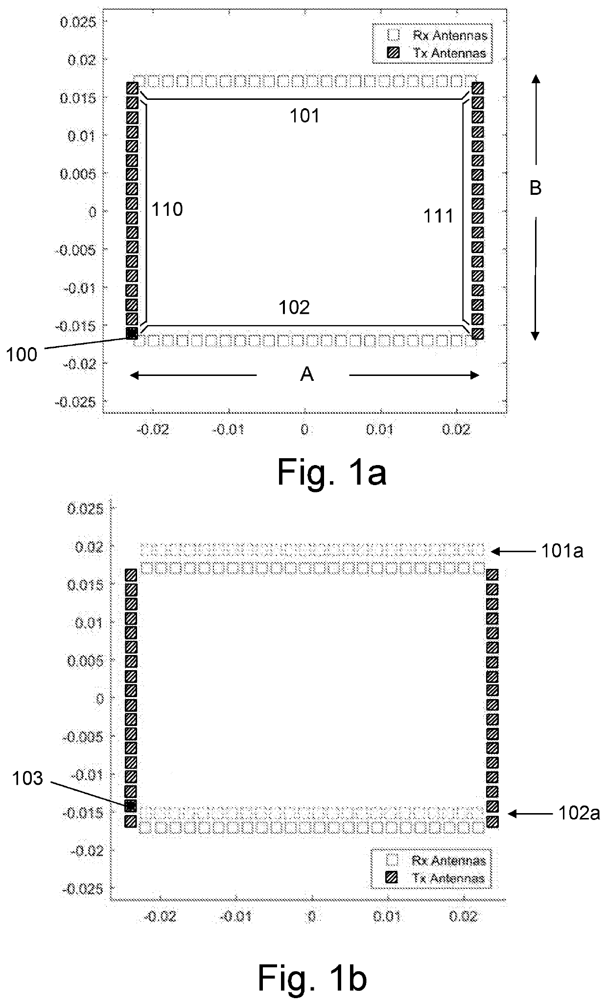
[0030]The present invention provides a high resolution compact radar switch array antenna design with high azimuth and elevation angular accuracy and increased effective aperture and reduced unwanted side-lobes, using a low number of transmit (Tx) and receive (Rx) elements.

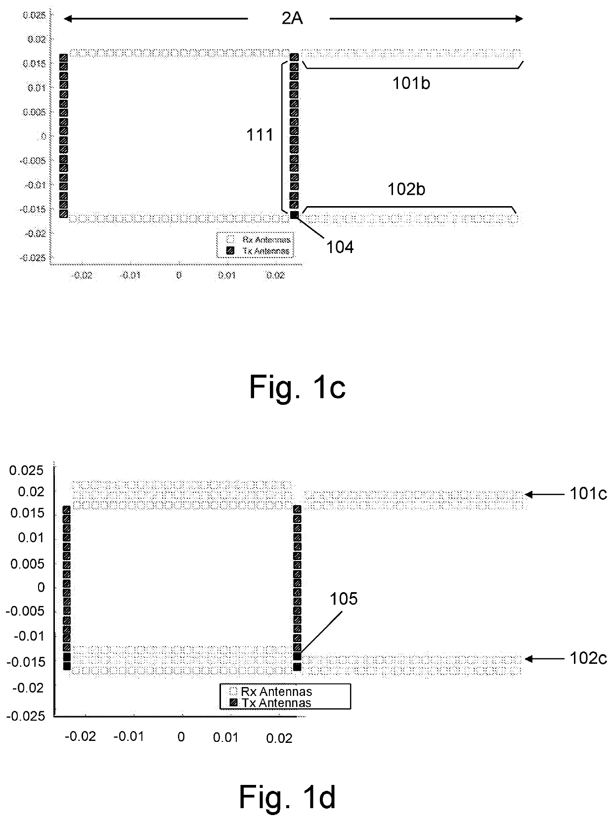
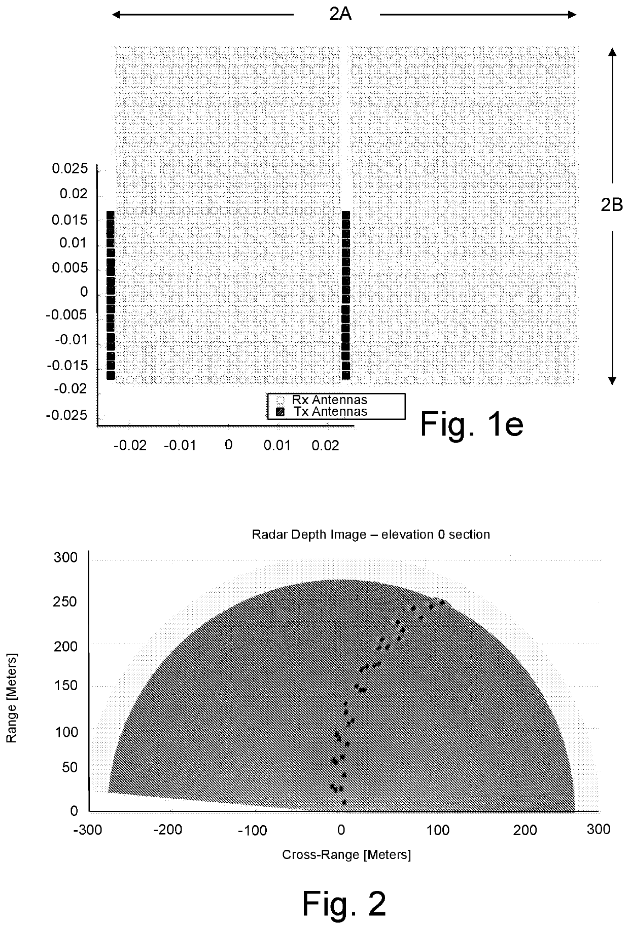
[0031]In order to obtain high resolution a phased array has been designed, based on the MIMO-SAR thin / full approach with Switched or non-switched Antenna Array (SAA). In this type of radar there are several transmitting array elements, which are activated at different times or simultaneously using orthogonal waveforms and a set of receiving array elements from which the data is collected simultaneously. In order to achieve high resolution, the radar should have a large aperture with respect to the carrier signal wave length (for 79 GHz λ=0.4 cm). Moreover, for full 3D sensing the large aperture is necessary in both azimuth and elevation. To obtain the maximal aperture in both directions, while minimizing the amoun...


PUM


Abstract

A method for increasing the effective aperture of radar switch / MIMO antenna array, using a low number of transmit (Tx) and receive (Rx) army elements, according to which an array of radar physical receive (Rx) / Transmit (Tx) elements are arranged in at least two opposing Rx rows and at least two opposing Tx columns, such that each row includes a plurality of receive (Rx) elements uniformly spaced from each other and each column includes a plurality of transmit (Tx) elements uniformly spaced from each other, the array forming a rectangular physical aperture. Used as a switch array, a first Tx element from one column is activated to transmit a radar pulse during a predetermined time slot. Reflections of the first transmission are received in all Rx elements, thereby virtually replicating the two opposing Rx rows about an origin determined by the location of the first Tx element within the rectangular physical aperture. This process is repeated for all remaining Tx elements during different time slots, thereby virtually replicating the two opposing Rx rows about an origin determined by the location of each activated Tx element within the rectangular physical aperture, while each time, receiving reflections of the transmission from each Tx element in all Rx elements. This way, a rectangular virtual aperture having dimensions which are twice the dimensions of the rectangular physical aperture is paved with replicated two opposing Rx rows. This virtual aperture determines the radar beam widths and side-lobes.

Description

FIELD OF THE INVENTION[0001]The present invention relates to the field of imaging radars. More particularly, the invention relates to a compact radar switch array antenna with high azimuth and elevation angular resolution, and increased effective aperture.BACKGROUND OF THE INVENTION[0002]In recent years many industries are moving to autonomous solutions such as the automotive industry, deliveries etc. These autonomous platforms should operate in the environment while interacting with both the stationary and moving objects. For this purpose these systems require a sensor suite which allows them to sense their surrounding in a reliable and efficient manner. For example, in order for an autonomous car to plan its route on a road with other cars on it, the trajectory planner must have a 3D map of the environment with indication of moving objects. Visual sensors are also degraded by bad weather and poor visibility (e.g. fog, smoke, sand, storm etc.). They are also limited in estimating r...

Claims


Application Information

Patent Timeline
IPC IPC(8): G01S13/34G01S13/93H01Q21/08H04B7/0413H01Q1/32G01S13/10G01S13/42
CPCH01Q21/08H04B7/0413G01S13/931G01S13/42G01S13/34H01Q1/3233G01S13/106H01Q21/28G01S7/03G01S7/2813G01S13/003
Inventor ARKIND, NOAMBARON, AMOSSTETTINER, YORAM
Owner ARBE ROBOTICS LTD
Features
  • R&D
  • Intellectual Property
  • Life Sciences
  • Materials
  • Tech Scout
  • Unparalleled Data Quality
  • Higher Quality Content
  • 60% Fewer Hallucinations
Learn More