Press ring with elongated holes

a technology of elongated holes and press rings, which is applied in the direction of pipe joints, non-disconnectible pipe joints, pipe joints, etc., can solve the problems of potential risk of malfunction, inability to safeguard tubular workpieces, and increased risk of damage to tubular workpieces or press rings, so as to improve the stability of bolt-hole connection, the effect of simple manufacturing of elongated holes

Active Publication Date: 2020-01-09
VON ARX AG
View PDF0 Cites 0 Cited by
  • Summary
  • Abstract
  • Description
  • Claims
  • Application Information

AI Technical Summary

Benefits of technology

[0018]In another preferred embodiment, each bolt comprises a recess which comprises a guiding contour; and wherein each elongated hole comprises a driving protrusion, extending towards each bolt; and wherein the driving protrusion is located in the recess when the rotation angle is larger than the closing angle and wherein the guiding contour is formed to guide the driving protrusion and formed to press the driving protrusion against the bolt when the rotation angle is smaller than the closing angle; and wherein the driving protrusion is located outside the recess and pressed against the bolt when the press ring is closed. When the movable press jaw is in an open condition, the driving protrusion can be housed in the recess and the movable press jaw can be freely movable, which includes for instance a rotational movement around the bolts and a translational movement within the pressing plane. The driving protrusion can be provided as an integral part of the inner walls of the surface of the elongated holes or it can be provided as a separate part, arranged such that it protrudes towards the lateral surface of the bolt during pressing operation. When the press ring arrives at the position, where the rotation angle of the movable press jaw becomes at most the closing angle, the protrusion contacts the surface of the bolt and a further closing of the movable press jaw leads to a guidance of the protrusion along the guiding contour. The guiding contour is formed such that the protrusion can apply a force to the bolt which results in a translational displacement of the bolt in the elongated hole. Herein, an increasing pressure can be applied the further the press ring closes, in turn leading to a further translation of the bolt in the elongated hole. Further, the guiding contour can be formed that the protrusion is guided outside the recess, when the press ring arrives at its fully closed position. At this point a maximum force is applied to the bolt which accordingly forces the bolt towards its final position where it abuts the inner surface of the elongated hole, proximate to the distal ends of the movable press jaw. The protrusion and the recess can also be shaped in a way that the protrusion is not guided outside the recess when the press ring is in its fully closed condition. The pressure of the protrusion holds the bolt in place such that no translational backwards movement is possible. It is also possible that the protrusion can be formed such that it also comprises a respective guiding contour which is adapted to engage with the opposite guiding contour of the recess to allow a smooth guidance of the protrusion in the recess. The protrusion can also be a driving bolt, partially located in a respective hole located adjacent to the elongated hole. This has the advantage of a simple manufacturing of the elongated holes since the elongated hole can simply be milled into the press jaw.
[0019]In another preferred embodiment, only a part of the length of the bolt is provided with the recess. The recess must not necessary be provided over the whole length of the bolt. It can be advantageous to only provide the recess at a portion of the bolt, for instance at the top portion, where the respective protrusion is provided and should be housed. Further, the protrusion might also not be provided over the whole length of the inner wall of the elongated hole but only at the portion where the recess of the bolt is provided. This increases guidance of the bolt and the hole in the area where no recess and protrusion is provided. In particular, in the portion, where no protrusion or recess are provided, stability of the bolt-hole connection can be increased since the contact is established at a larger surface during a rotational movement of the movable press jaws.
[0020]In another preferred embodiment, the bolts are formed as separate parts and affixed to the corresponding jaw or wherein the bolts and the corresponding jaws are integrally formed. An integral formation of the bolts leads to a higher resistance against mechanical stresses, which occur during the pressing operation. However, it is also possible to produce the bolts as separate parts and affix them to the corresponding jaw, for instance by press-fitting them into respective holes of the press jaw, which are correspondingly formed to house the bolts. This has the advantage that both parts, the bolts and the jaws, can be produced as less complex parts, which reduces manufacturing costs. Further, a separate exchange of any damaged or worn out parts can be enabled.
[0021]In another preferred embodiment, all parts of the press ring can be produced by milling. The press ring according to the present invention comprises a simple design, wherein only a few parts are necessary to transfer high pressing forces to a workpiece in a homogenous manner. Hence, the jaws can simply be produced at common milling machines and the bolts can be produced at automatic lathes. The so achieved reduced complexity of all parts not only reduces the manufacturing costs, it also facilitates the assembly of the press ring. Even further, the press ring according to the invention comprises an increased resistance against pollution and no extensive cleaning is needed to maintain the press ring fully functional. Since no covered surfaces are provided in the press ring any polluting parts, such dust or dirt, can simply fall out the press ring. This improves safety of the usage and increases the durability of the press ring.
[0022]In another preferred embodiment, the at least two movable press jaws are identically formed. The design further allows that the movable press jaws can be produced as completely identical parts, since the same movable press jaw can be used to function as one of the at least two movable press jaws by a simple, mirror inverted assembly of the respective press jaw. Hence, a production of the single parts can be performed very cost effective and replacement of a movable press jaw is facilitated.
[0023]Further, the invention relates to a method of pressing a tubular workpiece with a press ring according to the invention. As already discussed above, a pressing operation utilizing the press ring according to the invention is very time efficient. It can allow a halving of the time needed to perform the pressing because of the small closing angle. Further the displacement of the at least two movable press jaws relative to the at least one connecting press jaw in direction of the distal ends leads to a significant reduction of embossments at the area of the hinges and the area of the opening of the press ring because of a homogenous force distribution, when the press ring is driven into closed condition. Further the method according to the invention only requires to rotate the distal ends of the movable press jaws towards each other to acquire a proper pressing. During pressing no further alignment of the press ring and / or the tubular workpiece are needed as the press ring is self-aligning during the pressing operation.

Problems solved by technology

If a movement of the jaws perpendicular to the pressing plane would occur, proper pressing of the tubular workpiece could not be safeguarded and the risk of damaging either the tubular workpiece or the press ring would arise.
Not doing so would result in a non-uniform force distribution and hence lead to the potential risk of malfunctioning and accordingly to damages of the tubular workpiece and / or the press ring and / or a user.
In common press rings, insufficient force could be applied to the opening portion, where the two distal ends of the movable press jaws contact each other.

Method used


Image

  • Press ring with elongated holes
  • Press ring with elongated holes
  • Press ring with elongated holes

Examples


Embodiment Construction

[0030]In the following the present invention will now be described in more detail hereinafter with reference to the accompanying figures, in which exemplary embodiments of the invention are illustrated. However, the present invention may be embodied in different forms and should not be construed as limited to the embodiments set forth herein. Rather, these examples are provided so that this disclosure will be thorough and will convey the scope of the invention to persons skilled in the art. In the figures, the same reference signs refer to the respective same features.

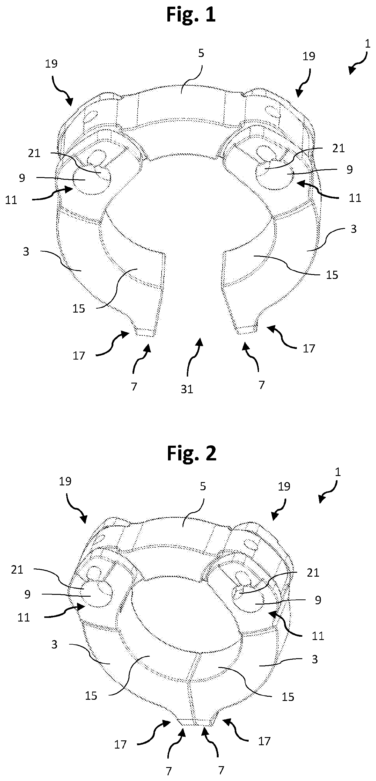
[0031]FIG. 1 shows the press ring 1 in a three-dimensional top view in an open condition. The press ring 1 comprises two movable press jaws 3 connected to a connecting press jaw 5 at the proximal ends 7 of the connecting press jaw 5. The inner surfaces of the jaws form a pressing surface 15, which can contact a tubular workpiece (not shown) to be pressed, which can be arranged in the press ring 1. The bolts 9 extend pe...


PUM

PropertyMeasurementUnit
closing angleaaaaaaaaaa

Abstract

A press ring (1) for pressing tubular workpieces (35), comprising: at least two movable press jaws (3); and at least one connecting press jaw (5) connecting the movable press jaws (3); wherein the movable press jaws (3) are each hinged at their proximal ends to the connecting press jaw (5) by means of respective bolts (9), so that the distal ends (7) of the movable press jaws (3) can be rotated towards and away from each other to close respectively open the press ring (1) to receive a workpiece (35) therein, and characterized in that the respective bolts (9) are arranged in elongated holes (11), allowing a translational displacement of the bolts (9) in the elongated holes (11) upon rotating the movable press jaws (3).

Description

1. FIELD OF THE INVENTION[0001]The present invention relates to a press ring and a method for pressing tubular workpieces, in particular a press ring which comprises elongated holes to connect at least two movable press jaws with at least one connecting press jaw.2. TECHNICAL BACKGROUND[0002]Press tools or press rings comprising press jaws can be used to press tubular workpieces together to achieve a safe and reliable connection. These type of connections can be used in several fields of applications where it is necessary to interconnect different types of tubes for instance to allow a transport of liquids or gases through the inner cavities of the tubes. For the connection of end portions of tubes, often tubular sleeve-like workpieces are used, which can be made of a metal or any other suitably compressible material and which are put over the respective ends of the tubes to be connected. By applying a radial pressure from the outside, the contact surfaces of the workpiece and the t...

Claims


Application Information

Patent Timeline
Patent Type & Authority Applications(United States)
IPC IPC(8): B21D39/04B25B27/10
CPCB21D39/048B25B27/10F16L2013/145
Inventor SCHWEIZER, BEATSTUCKI, ANDREASHEER, MARIANNE
Owner VON ARX AG
Why Eureka
Try Eureka