Method for operating multi-bar linkage mechanism based conveyor

a technology of linkage mechanism and conveyor, which is applied in the field of conveyors, can solve the problems of low stability, high safety hazards, and inability to operate such vessels, and achieve the effects of avoiding the loss of stability of the whole system, simple operation of automatic control system, and concise overall structure of conveyor

Active Publication Date: 2020-01-09
CHANGSHA UNIVERSITY OF SCIENCE AND TECHNOLOGY
View PDF8 Cites 0 Cited by
  • Summary
  • Abstract
  • Description
  • Claims
  • Application Information

AI Technical Summary

Benefits of technology

[0028]The automatic control system is connected to the tension sensor arranged at an end of each steel wire rope. When tension information obtained by the tension sensor indicates a risk value, the whole conveyor may be controlled by the automatic control system to stop operating. The second two-drum winch 6 is connected to a gantry pulley arranged at an upper end of the gantry via a steel wire rope. A tension sensor is arranged at an end of the steel wire rope. The stability of the whole gantry system 1 is determined through the tension sensor, to avoid the loss of stability of the whole system. Both an angle of pulling of the whole conveyor and the stability of the gantry system 1 are controlled by the automatic control system, by analyzing the information from the tension sensor. In this way, the automatic control and the safety monitoring are realized. The roller unit 5 comprises upper bearing rollers 8, lower return rollers 9 and reversing rollers 10. The upper bearing rollers 8 are uniformly mounted on the cross-bar on the surface of the boom. The lower return rollers 9 are mounted on the cross-bar on the bottom of the boom. The reversing rollers 10 are mounted at a forefront end of the conveyor boom 2. Automatic tensioning can be realized since the multi-bar linkage mechanisms 201 of the multi-bar linkage mechanism based conveyor boom 2 are stretched. No tensioning device is required, so that it is simpler to operate the automatic control system. The overall structure of the conveyor is more concise.
[0029]By obtaining, in real time, stressed deformation information of each multi-bar linkage mechanism 201 from the tension sensor by using the automatic control system during the operation of the conveyor, the multi-bar linkage mechanism based conveyor boom 2 is controlled and monitored precisely. Accordingly, risk factors can be found in time. This can reduce the fault probability and ensure the operating efficiency of the conveyor because the operators can carry out repairs in advance. Furthermore, the whole conveyor is automatically controlled by a programmable control system.
[0030]Compared with the prior art, the method for operating a multi-bar linkage mechanism based conveyor according to the above technical solution has the following beneficial effects. The operating mode for a multi-bar linkage mechanism based conveyor comprises following modes: a hydraulically-driven mode, a winch-driven mode, a stretch and retraction adjustment mode, a bearing adjustment mode and a counterweight adjustment mode. The operating method comprising those modes that are cooperated with each other realizes higher safety and better stretch and retraction performance. Compared with the integral trussed boom and the scissor fork mechanism used in the prior art, due to the stretch and retraction adjustment mode, the multi-bar linkage mechanism based conveyor boom 2 has the following advantages: first, the stretch and retraction length is adjustable so that the applicable range is wider; second, the overall structure is simple and the structural modularization is convenient for production and assembly; third, the deformation under load is low; fourth, since a tension sensor is arranged at an end of the steel wire rope, when the multi-bar linkage mechanism based conveyor boom 2 is to be retracted, automatic control can be realized by the automatic control system, thus the operating difficulty of the operators is greatly decreased, and the safety in operating the device is significantly improved; due to the counterweight adjustment mode, this operating method is more cost-effective; and due to the bearing adjustment mode, based on the excellent performance of the multi-bar linkage mechanisms 201, the operating range of the conveyor is further expanded. In the multi-bar linkage mechanism based conveyor, by changing the retraction of the multi-bar linkage mechanism based conveyor 2 to horizontal retraction, the operation is simpler and more convenient than the integral overturning mode and the folded overturning mode; and during the sand unloading, the boom is higher in safety. Furthermore, no tensioning device is required. This reduces loads on the boom. Moreover, it is easy to realize automatic adjustment of the tension and deviation of the conveyor belt, high retraction efficiency, more reliable safety factor, low maintenance and use costs, etc.

Problems solved by technology

However, the instability of such vessels also has become increasingly prominent.
However, the conveyor boom of a conventional self-unloading vessel may have a length up to 40 m, but it cannot be retracted, resulting in low stability and high safety hazard.
For example, since accidents frequently occur in the conventional overhung belt racks, the insurance for belt racks had been refused by insurance companies in China.
However, due to the use of the integral trussed boom that is fixed in length, the conveying distance is not adjustable.
Although the integral overturning mode is simpler and more convenient than the folded overturning mode, the overturned conveyor arm is suspended, not firmly fixed, resulting in high safety hazard.

Method used


Image

  • Method for operating multi-bar linkage mechanism based conveyor
  • Method for operating multi-bar linkage mechanism based conveyor

Examples


Embodiment Construction

[0057]The present invention will be further described below with reference to the accompanying drawings by specific embodiments.

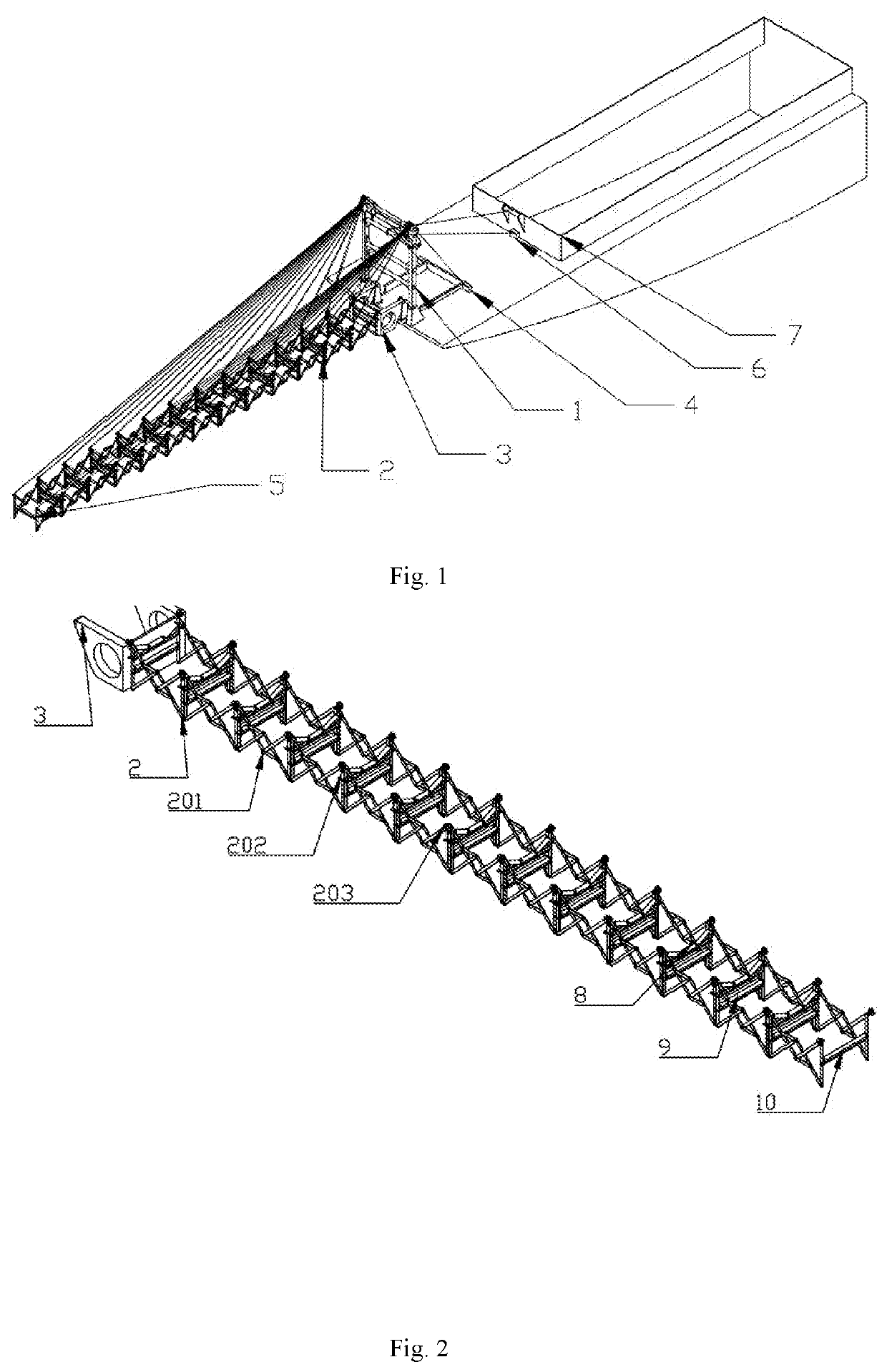
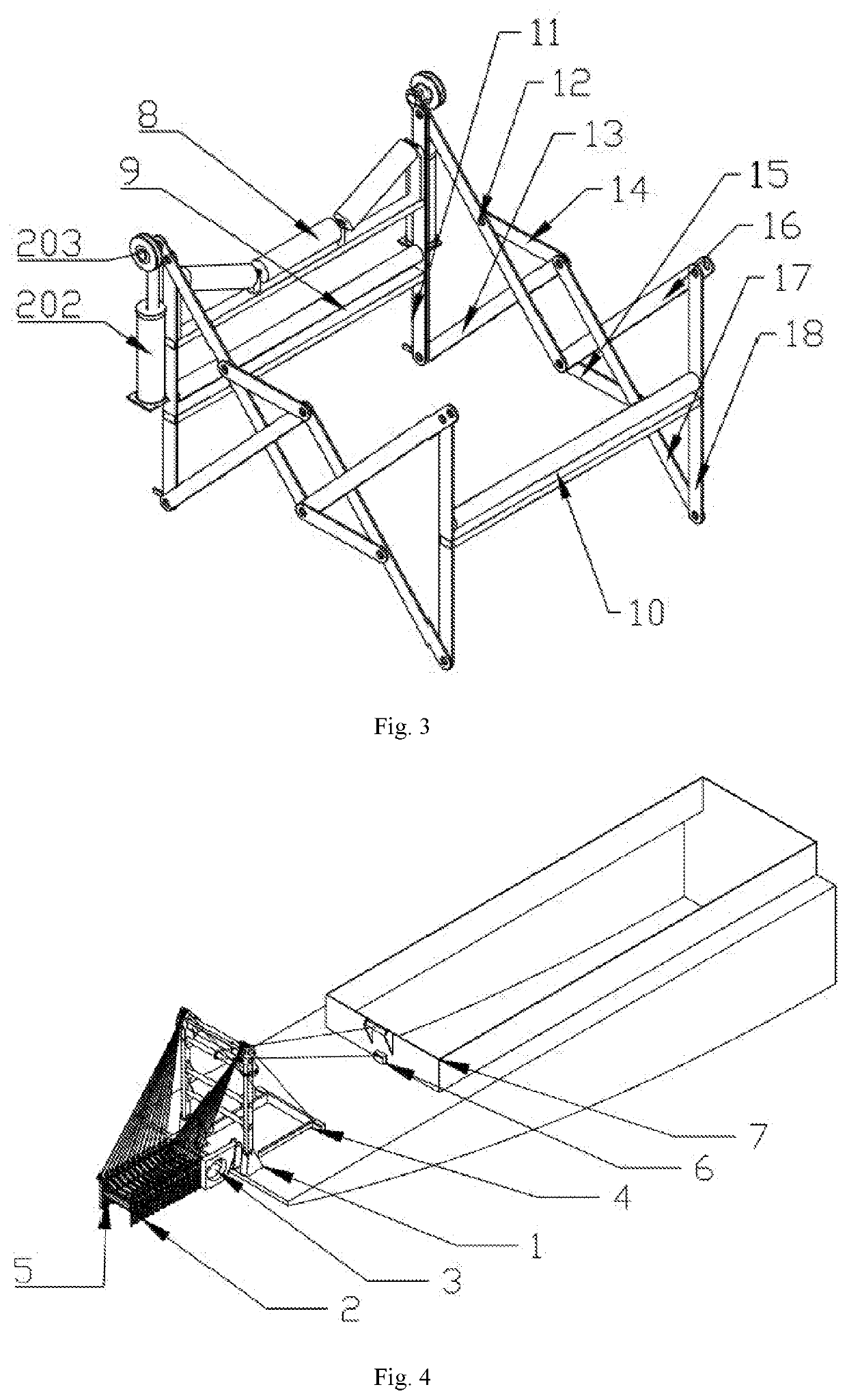
[0058]An embodiment of the present invention will be described below. A method for operating a multi-bar linkage mechanism based conveyor is provided. The conveyor comprises a gantry system 1, a gantry, a set of gantry pulleys, gantry pulleys, a gantry support, a multi-bar linkage mechanism based conveyor boom 2, a boom support 3, a first two-drum winch 4, a roller unit 5, a second two-drum winch 6 and an automatic control system. The multi-bar linkage mechanism based conveyor boom 2 comprises multi-bar linkage mechanisms 201, hydraulic cylinders 202 and pulleys 203, wherein the pulleys 203 are in a composite structure of carbon fibers and carbon steel. The multi-bar linkage mechanism based conveyor boom 2 is articulated with the boom support 3. The multi-bar linkage mechanism based conveyor boom 2 comprises a plurality of multi-bar linkage mechanisms 201 e...


PUM


Abstract

The present invention discloses a method for operating a multi-bar linkage mechanism based conveyor. Stretching the mechanism based conveyor comprises: an automatic control system is started to control a first two-drum winch, a second two-drum winch, and hydraulic cylinders in a multi-bar linkage mechanism based conveyor boom to operate together until the mechanism enters an operating state, and the first two-drum winch, the second two-drum winch, and the hydraulic cylinders in the multi-bar linkage mechanism based conveyor boom stop operating. Then, the angle of the multi-bar linkage mechanism based conveyor boom can be adjusted by controlling the operation of the second two-drum winch. Retracting the mechanism based conveyor comprises: the automatic control system is started to control the first two-drum winch, the second two-drum winch, and the hydraulic cylinders in the multi-bar linkage mechanism based conveyor boom to operate together until the mechanism enters a non-operating state.

Description

CROSS-REFERENCE TO RELATED APPLICATIONS[0001]This application is a continuation of International Patent Application No. PCT / CN2019 / 079665, filed on Mar. 26, 2019, which claims the benefit of priority from Chinese Patent Application No. 201810275007.2, filed on Mar. 30, 2018. The contents of the aforementioned application, including any intervening amendments thereto, are incorporated herein by reference in its entirety.TECHNICAL FIELD[0002]The present invention relates to the technical field of conveyors for transport ships and in particular to a method for operating a multi-bar linkage mechanism based conveyor.BACKGROUND OF THE PRESENT INVENTION[0003]In recent years, inland sand unloading vessels have attracted widespread attention due to their advantages of flexible and quick cargo unloading performance. However, the instability of such vessels also has become increasingly prominent. Furthermore, due to large water coverage and rich waterway resources in China, inland sand unloadi...

Claims


Application Information

Patent Timeline
Patent Type & Authority Applications(United States)
IPC IPC(8): B65G67/60
CPCB65G67/60E01D15/24B65G69/2847B65G21/14B65G67/606B65G2814/0397
Inventor YIN, LAIRONGHUANG, JUANCAI, SHUOXU, PENGHU, LINPENG, XUEJUNJIANG, ANWEI
Owner CHANGSHA UNIVERSITY OF SCIENCE AND TECHNOLOGY
Why Eureka
Try Eureka