
Zoom lamp lens group

a technology of zoom lamp and lens group, applied in the optical field, can solve the problem of low optical efficiency and achieve the effect of improving illumination effect and ensuring optical efficiency

Inactive Publication Date: 2020-01-09
SELF ELECTRONICS CO LTD +2
View PDF0 Cites 0 Cited by
  • Summary
  • Abstract
  • Description
  • Claims
  • Application Information

AI Technical Summary

Benefits of technology

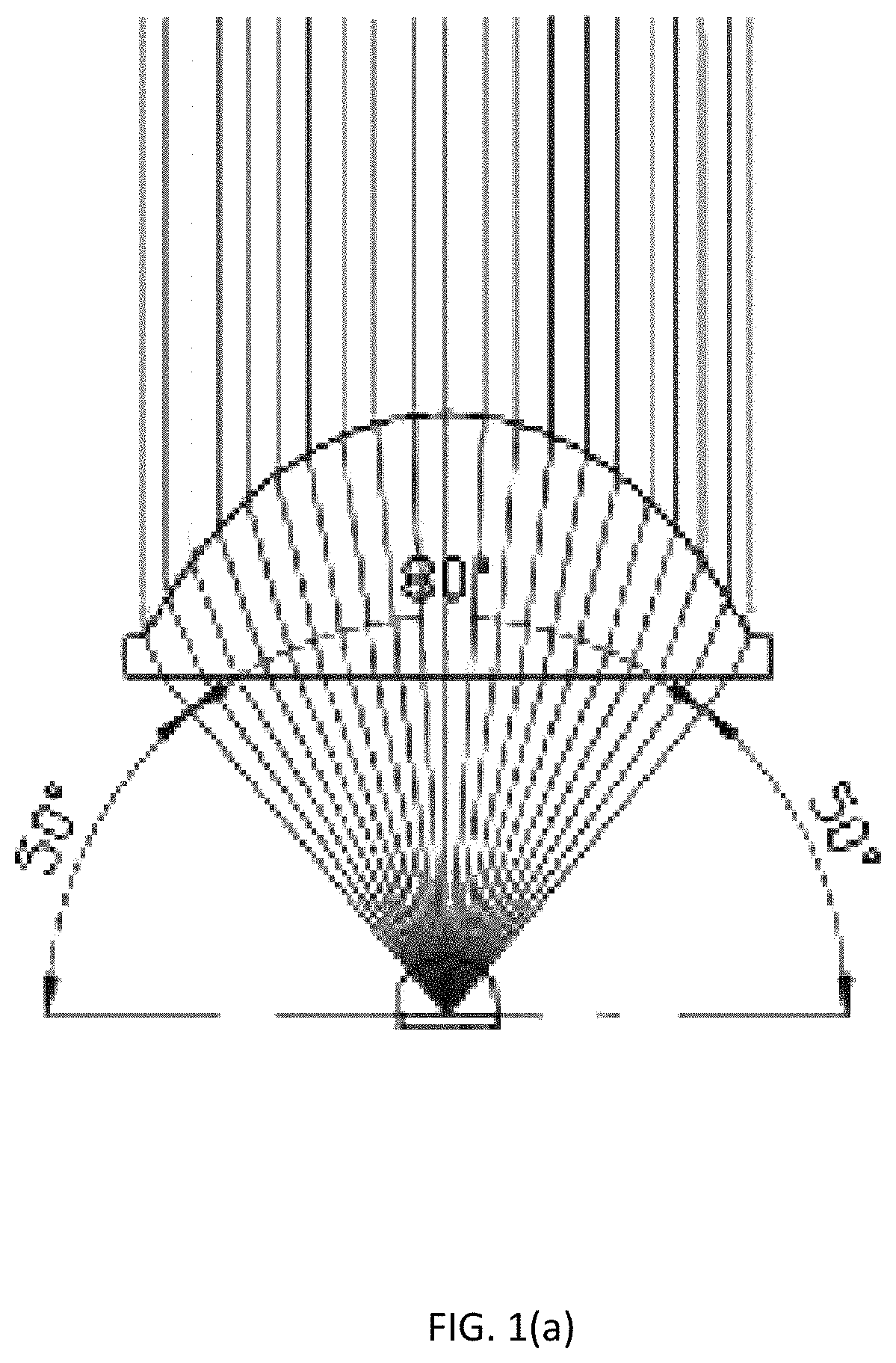
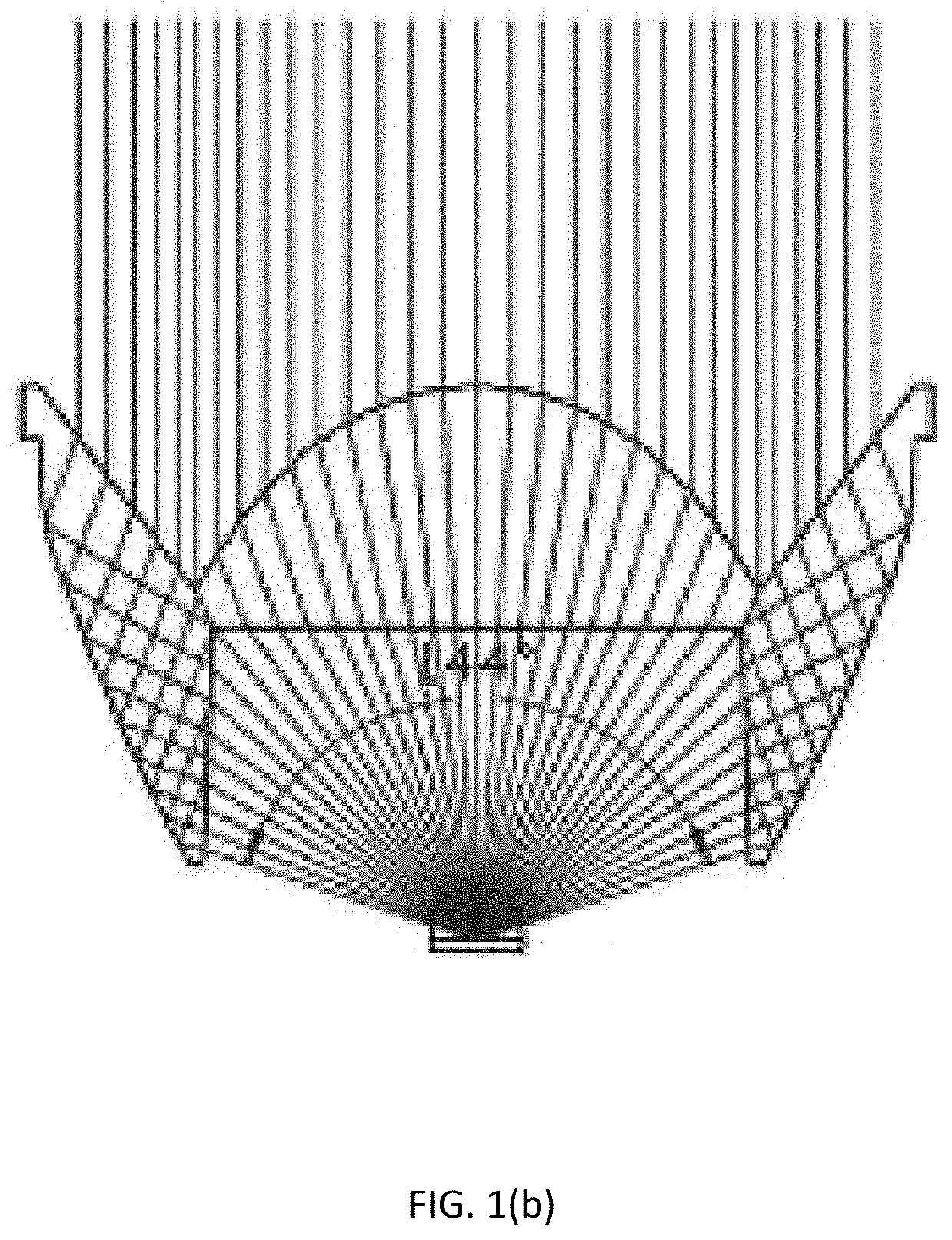
The invention has the advantage that it allows the first lens of the zoom lamp lens group to emit all the light emitted by the light source, ensuring optimal use of the light source. Additionally, the distance between the first lens and the light source is fixed, meaning that the position of the first lens does not need to be moved during dimming. This simplifies the adjustment of the illumination angle of the illumination system, as only the distance between the convex lens and the concave lens with the same refractive index and radius in the lens assembly needs to be changed. This also eliminates the issue of spot layering which can occur when using a total reflection lens and a convex lens with respect to the light source. As a result, the illumination effect is improved.

Problems solved by technology

Although the light distribution method has a clear spot and a good illumination effect, the optical efficiency is low.

Method used


Image

  • Zoom lamp lens group
  • Zoom lamp lens group
  • Zoom lamp lens group

Examples


Embodiment Construction

[0032]Embodiments of the invention are described in detail below, Examples of the embodiments are shown in the appended drawings in which consistently identical or similar labels represent identical or similar elements or elements having the same or similar function. The embodiments described below by reference to the drawings are exemplary and are only used for the interpretation of the invention and cannot be understood to be a limitation of the invention.

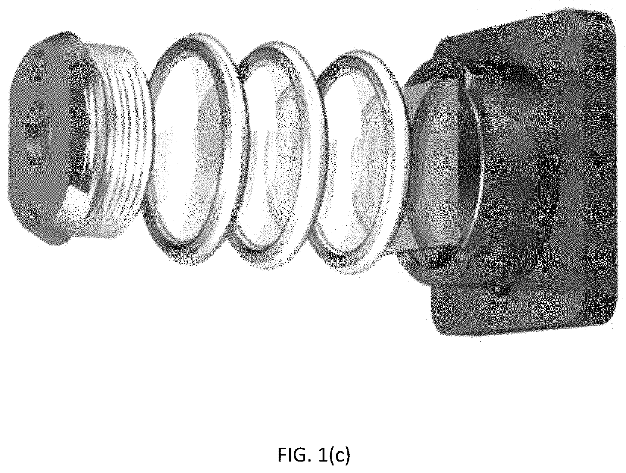
[0033]FIG. 2 and FIG. 3(a)-3(d) show the structure of an embodiment of the lens group of zoom lamp and corresponding lighting system in the present application. The lens group of zoom lamp in the present application includes a first lens capable of emitting all the light emitted by the light source, a lens assembly located on the light exiting side of the first lens and capable of obtaining different illumination angles by adjusting the spacing between the internal devices thereof, the distance between the first lens and the ligh...


PUM


Abstract

The present invention relates to a zoom lamp lens group, the zoom lamp lens group includes a first lens with a fixed distance from the light source and capable of emitting all light rays of the light source, and a lens assembly located on a light exiting side of the first lens; the lens assembly includes at least one concave lens and at least one convex lens located between the first lens and the concave lens; the convex lens has the same radius and refractive index as the concave lens, and the convex surface of the convex lens is disposed opposite to the concave surface of the concave lens, and the distance between the convex lens and the concave lens is adjustable to obtain different illumination angles. By using this lens group, the light efficiency is improved and the irradiation effect is good.

Description

RELATED APPLICATION[0001]This application claims priority to a Chinese Patent Application No. CN 201810727568.1, filed on Jul. 4, 2018.FIELD OF THE TECHNOLOGY[0002]The present invention relates to optical field, with particular emphasis on a zoom lamp lens group.BACKGROUND OF THE INVENTION[0003]With the wide application of LED lamps, higher requirements have been put forward for LED lighting. Such as shopping malls, counters and other occasions, the lamps are required to have soft and flexible light to avoid glare and prevent visual pressure on customers. In street lighting, especially in smog weather, it is hoped that the light emitted by the lamps can be illuminated far enough and has sufficient penetrating power.[0004]It is well known that one of the important factors affecting the light efficiency is the angle of the light emitting light. In order to meet different requirements of light efficiency, people try to perfect the lighting effect by designing different zoom lens and ch...

Claims


Application Information

Patent Timeline
Patent Type & Authority Applications(United States)
IPC IPC(8): F21V14/06F21V5/00F21V5/04
CPCF21V14/06F21V5/008F21V5/046F21V5/048F21V7/0091F21Y2115/10F21V5/045G02B7/10G02B19/0028G02B19/0061G02B15/142
Inventor HE, ZUPING
Owner SELF ELECTRONICS CO LTD
Learn More