Flat fluorescent lamp for display devices

a fluorescent lamp and display device technology, applied in the field of flat fluorescent lamps, can solve the problems of inability to insert electrodes, inconvenient use, and inability to discharge plasma, and achieve the effect of improving the discharge efficiency of ffl and high brightness

Inactive Publication Date: 2008-03-04
MATHBRIGHT TECH
View PDF6 Cites 0 Cited by
  • Summary
  • Abstract
  • Description
  • Claims
  • Application Information

AI Technical Summary

Benefits of technology

[0010]Accordingly, the present invention has been made keeping in mind the above problems occurring in the related art, and an object of the present invention is to provide a flat fluorescent lamp (FFL) for display devices, which has an improved plasma discharge electrode structure configured to provide an operational effect expected from a reduction in the distance between electrodes provided at opposite ends of plasma discharge channels although the real distance between the electrodes is not reduced, and which is efficiently operated using a low voltage and has an optical efficiency and a plasma discharge efficiency higher than predetermined levels.
[0011]Another object of the present invention is to provide a flat fluorescent lamp (FFL) for display devices, which has various electrode structures able to efficiently generate interelectrode plasma discharge.

Problems solved by technology

However, the electrodes 104a provided at opposite ends of the channel 103a of the IEFL are problematic in that it is difficult to insert the electrodes 104a into and fix them in the ends of the channel 103a during an FFL manufacturing process.
However, although the above-mentioned serpentine channel defining the long plasma discharge space of an FFL with electrodes provided at opposite ends of the channel provides of the FFL with high optical power and high optical efficiency, the long plasma discharge space undesirably causes a problem in that the plasma discharge start voltage and the plasma discharge drive voltage are undesirably increased.
This increases the electric power consumption of the FFL due to the intrinsic properties of the FFL having low optical efficiency relative to the high voltage applied to the electrodes, and reduces both the expected life span and the operational reliability of the FFL, and retards the commencement of operation of the FFL.
However, the reduction in the interelectrode distance in the FFL undesirably degrades the plasma discharge efficiency and reduces the size of the FFL.

Method used


Image

  • Flat fluorescent lamp for display devices
  • Flat fluorescent lamp for display devices
  • Flat fluorescent lamp for display devices

Examples


first embodiment

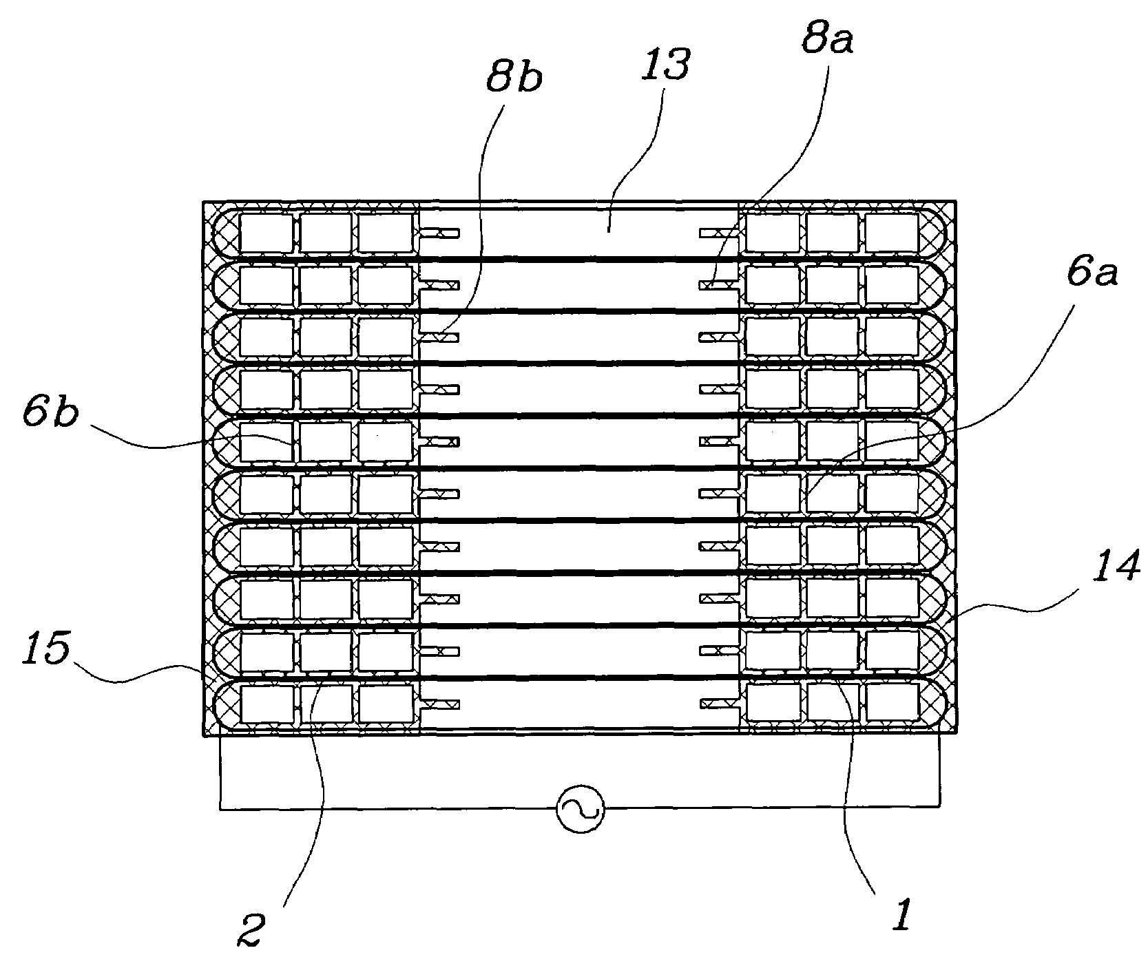
[0048]As shown in FIGS. 5 through 7, the branch electrodes 1 and 2 according to the present invention extend from the main electrodes 14 and 15 a predetermined identical length of about ⅓ of the length of each discharge channel 13. The branch electrodes 1 and 2 may be provided on the lower surface of a lower plate 12 along predetermined lines corresponding to the boundaries of the channels 13 defined by both the junction lines between the channels 13 and the outside edges of the two outermost channels 13 which are the outside edges of the lamp body. The above-mentioned boundaries of the channels 13 are included in non-discharge zones where plasma discharge does not occur. A fluorescent material may be coated on the external surfaces of the boundaries of the channels 13.

[0049]Due to the branch electrodes 1 and 2 extending from the main electrodes 14 and 15 toward the opposite main electrodes 15 and 14, an effect expected from a reduction in the distance between the main electrodes 14...

fourth embodiment

[0053]As illustrated in FIG. 10 showing an FFL having branch electrodes according to the present invention, a pair of branch electrodes 4a and 4b may be provided on the lower surface of a lower plate 12 along lines within a region corresponding to each discharge channel 13. The pair of narrow branch electrodes 4a and 4b longitudinally and parallely extends from associated main electrodes 14 and 15 in opposite directions to approach opposite main electrodes and spaced apart from each other in a transverse direction of each channel 13. Due to the pairs of branch electrodes 4 each comprising the branch electrodes 4a and 4b, an electric field is induced in each channel 13 in the transverse direction perpendicular to the longitudinal axis of the channel 13 when an AC voltage is applied to the main electrodes 14 and 15. Thus, the branch electrodes 4a and 4b reduce the drive voltage for the FFL and improve optical efficiency, and maintain brightness constantly over the whole area of the FF...

fifth embodiment

[0054]As illustrated in FIG. 11 showing an FFL having branch electrodes according to the present invention, the branch electrodes 5a and 5b may be provided on the upper surface of a lower plate 12 at positions corresponding to central positions around the ends of the discharge channels 13. In this embodiment, the main electrodes 14 and 15 may be provided on the upper surface of the lower plate 12 to agree with the branch electrodes provided on the upper surface of the lower plate. The branch electrodes 5a and 5b having short lengths and sharp tips protrude from the main electrodes 14 and 15 in opposite directions towards the opposite main electrodes 15 and 14. The above-mentioned branch electrodes 5a and 5b more efficiently emit electric charges.

[0055]In the present invention, the FFL may be provided with both joint electrodes and step electrodes which are electrically coupled to the branch electrodes, as shown in FIGS. 12 through 15.

[0056]As illustrated in FIGS. 12 and 13, the join...


PUM

PropertyMeasurementUnit
optical efficiencyaaaaaaaaaa
energyaaaaaaaaaa
optical poweraaaaaaaaaa

Abstract

A flat fluorescent lamp (FFL) for display devices, which has an improved electrode structure for plasma discharge, thus being efficiently operated using a low voltage and having high optical efficiency, is disclosed. The FFL of the present invention is provided with a plurality of branch electrodes extending from main electrodes, provided on opposite ends of a lamp body, in opposite directions toward the opposite main electrodes and being parallel to longitudinal axes of the discharge channels. Furthermore, the FFL may include joint electrodes which electrically couple the branch electrodes, provided around each of the opposite ends of the lamp body, to each other. The FFL may further include step electrodes and / or inductive electrodes.

Description

BACKGROUND OF THE INVENTION[0001]1. Field of the Invention[0002]The present invention relates, in general, to flat fluorescent lamps used as backlight units in display devices and, more particularly, to a flat fluorescent lamp for display devices, which has an improved electrode structure for plasma discharge, thus being efficiently operated using a low voltage and having high optical efficiency.[0003]2. Description of the Related Art[0004]Generally, display devices have been classified into two types: emissive display devices and non-emissive display devices, according to their ability to emit light. Liquid crystal displays (LCD) widely used as flat panel display devices in recent years are examples of non-emissive display devices that cannot emit light themselves, so that the LCDs must be backed with backlight units (BLU).[0005]In recent years, flat fluorescent lamps (FFL) have been preferably and widely used as the BLUs for LCDs. The FFLs may be configured as internal electrode f...

Claims


Application Information

Patent Timeline
Patent Type & Authority Patents(United States)
IPC IPC(8): H01J63/04H01J11/00G02F1/13357H01J61/067H01J61/30H01J61/92H01J65/00
CPCH01J61/305H01J65/046
Inventor YOON, JAE DOO
Owner MATHBRIGHT TECH
Why Eureka
Try Eureka