Optical scanning device and image forming apparatus

Active Publication Date: 2020-01-09
KONICA MINOLTA INC
View PDF0 Cites 0 Cited by
  • Summary
  • Abstract
  • Description
  • Claims
  • Application Information

AI Technical Summary

Benefits of technology

This patent aims to solve the problem of image deterioration caused by positional displacement of a luminous flux incident upon an optical detection sensor in a device that collects light. The current technique involves using a light collecting lens, which causes heat and changes in the posture of the reflection mirror and the lens, leading to increased optical path length and cost. Increasing the number of reflection mirrors leads to non-negligible positional displacement and decreases design flexibility. The patent seeks to provide an alternative that can reduce size at low cost while suppressing image deterioration.

Problems solved by technology

When the scanning directions are opposite to each other, the posture of an optical element is changed due to installation errors, distortions in an apparatus caused by attachment to a body, and the like.
Such movements of the scanning lines in the opposite directions cause a displacement in superimposition of latent images by the first optical system and the second optical system, thereby consequently leading to a color deviation on an image, which is known as a common problem.
Furthermore, this heat also changes the posture of the light collecting lens placed in the vicinity of the deflector, and additionally, causes thermal expansion of the lens, thereby changing its optical performance.
When the position of the luminous flux incident upon the optical detection sensor is deviated, it becomes difficult to correctly detect the scanning start position of the luminous flux on the surface-to-be-scanned, so that a color deviation occurs in the image, which may lead to image deterioration.
However, when a light collecting lens is not used, the optical path to the optical detection sensor is increased in length.
Also, light collecting lenses are generally high-cost components.
Thus, when such a light collecting lens is used for each optical system, the apparatus may be increased in cost.
However, the increased number of reflection mirrors may lead to a non-negligible degree of positional displacement of the luminous flux incident upon the optical detection sensor that is caused by the posture change of the reflection mirror resulting from heat of the deflector, which may lead to image deterioration.
Thus, the apparatus may be further increased in cost.

Method used


Image

  • Optical scanning device and image forming apparatus
  • Optical scanning device and image forming apparatus
  • Optical scanning device and image forming apparatus

Examples


second embodiment

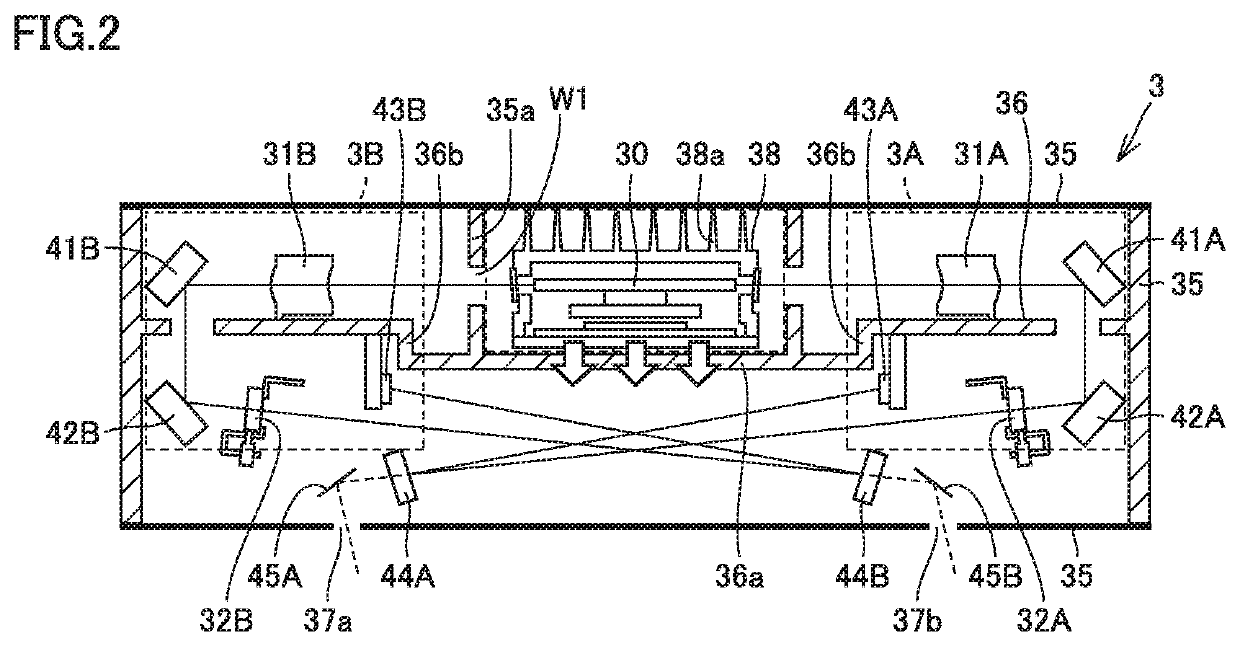
[0063]Referring to FIGS. 9 to 11, the configuration of optical scanning device 3 in the second embodiment will be hereinafter described. FIG. 9 is a cross-sectional view showing the internal structure of optical scanning device 3 in the main scanning direction. FIGS. 10 and 11 are the first and second cross-sectional views each showing the internal structure of optical scanning device 3 in the sub-scanning direction.

[0064]Referring to FIGS. 10 and 11, optical scanning device 3 in the present embodiment is provided with a coolant flow path CH formed to include deflector 30 and pass through housing 35. The coolant introduced into coolant flow path CH may be any coolant as long as it does not affect the performance of deflector 30, but may generally be air as a conceivable coolant.

[0065]In the configuration of the present embodiment, stepped portion 36b forms a part of a sidewall 35a of coolant flow path CH. Sidewall 35a is provided with a slit W1 through which a luminous flux passes. ...


PUM


Abstract

In an optical scanning device, a housing has a structure divided into an upper stage and a lower stage by a mounting plate on which a deflector, a first optical system and a second optical system are mounted. A first optical system reflection mirror and a second optical system reflection mirror are mounted in the other of the upper stage and the lower stage in which the deflector is not mounted. Each of the first optical system and the second optical system is disposed across a region including the upper stage and the lower stage. The first optical system reflection mirror and the second optical system reflection mirror are disposed with the deflector located therebetween. The first optical system reflection mirror is disposed on a side of the second optical system, and the second optical system reflection mirror is disposed on a side of the first optical system.

Description

[0001]The entire disclosure of Japanese Patent Application No. 2018-127610 filed on Jul. 4, 2018 is incorporated herein by reference in its entirety.BACKGROUNDTechnological Field[0002]The present disclosure relates to an optical scanning device and an image forming apparatus.Description of the Related Art[0003]There is a known optical scanning device using a so-called bilateral deflection system, including the first optical system and the second optical system with a deflector located therebetween, in which a luminous flux emitted toward the first optical system and a luminous flux emitted toward the second optical system are deflected on different reflection surfaces of the deflector for scanning. In contrast, there is a known optical scanning device using a so-called unilateral deflection system, including an optical system disposed only on one side of a deflector, in which a luminous flux is deflected on a single reflection surface of the deflector for scanning.[0004]In the optic...

Claims


Application Information

Patent Timeline
IPC IPC(8): G03G15/043G02B26/12G03G15/04G03G21/20
CPCG06K15/1228B41J2/473G02B26/123G03G15/04072G02B26/12G03G15/043G03G21/1666G02B7/008
Inventor HASEGAWA, RYOTANIGUCHI, HAJIME
Owner KONICA MINOLTA INC
Why Eureka
Try Eureka