
Tilted interferometric endpoint (IEP) window for sensitivity improvement

a technology of interferometry and sensitivity improvement, which is applied in the direction of electrical discharge tubes, semiconductor/solid-state device testing/measurement, electrical equipment, etc., can solve the problems of reducing the sensitivity of on-substrat metric etching, iep detection windows that are not oriented to the surface of the substrate, and only working over a limited wavelength rang

Inactive Publication Date: 2020-01-09
APPLIED MATERIALS INC
View PDF5 Cites 1 Cited by
  • Summary
  • Abstract
  • Description
  • Claims
  • Application Information

AI Technical Summary

Benefits of technology

The patent provides a tilted window for use in a processing chamber for detecting the endpoint of a process. The window is tilted at an angle relative to the substrate support surface, allowing for better optical coupling with an endpoint detection system. The invention enables improved accuracy and efficiency in processing.

Problems solved by technology

Unfortunately, conventional flat interferometry endpoint (IEP) detection windows encounter significant internal reflection and reduced sensitivity to on-substrate metrics while etching.
Unfortunately, ARCs only work over a limited range of wavelengths when it is necessary to remove internal reflections over a range of wavelengths, generally from 200 nm to 800 nm.

Method used


Image

  • Tilted interferometric endpoint (IEP) window for sensitivity improvement
  • Tilted interferometric endpoint (IEP) window for sensitivity improvement
  • Tilted interferometric endpoint (IEP) window for sensitivity improvement

Examples


Embodiment Construction

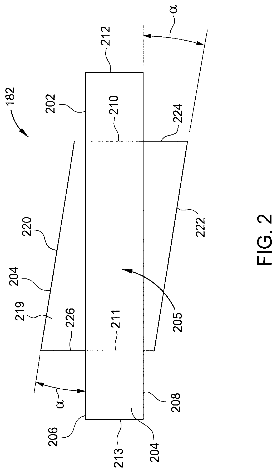
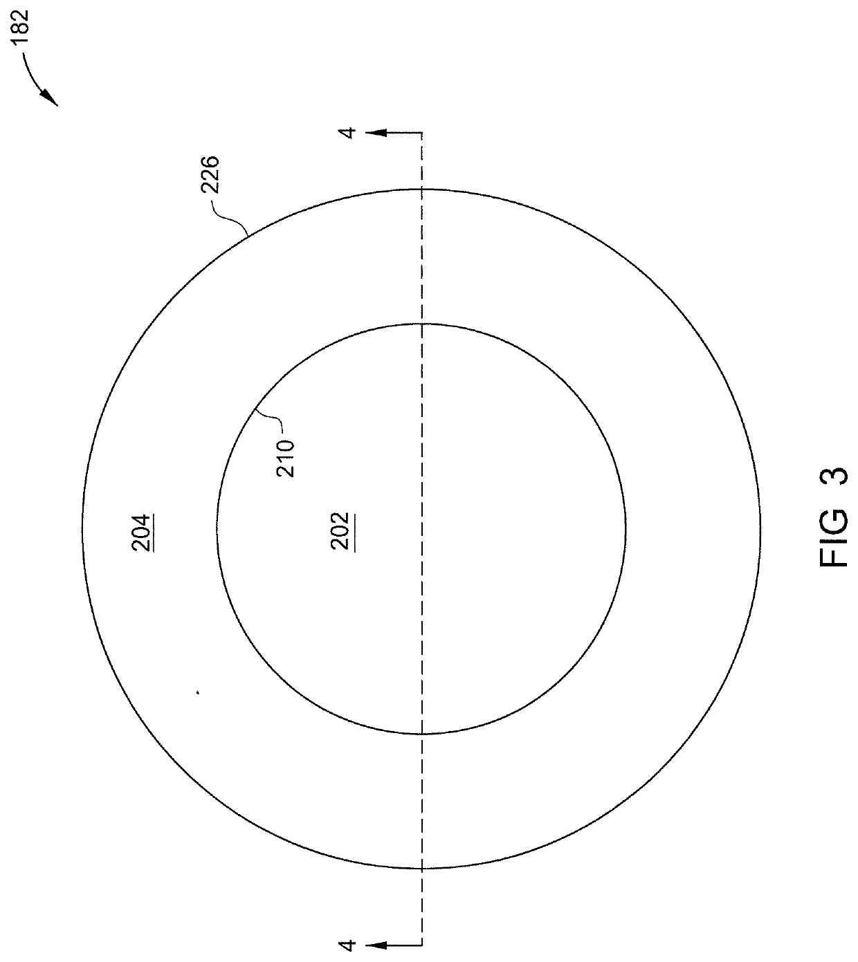
[0022]The titled window presented herein can effectively reduce internal reflections over a wide range of wavelengths of interest, such as between about 200 to 800 nm, without the need of anti-reflection coatings. The dynamic range of the IEP system is improved. The direct benefits of the tilted window are improved etch depth control accuracy and extended window life time. The tilted window is generally compatible with existing chamber bodies, and as such, may be retrofit into almost all existing chambers that utilize IEP systems.

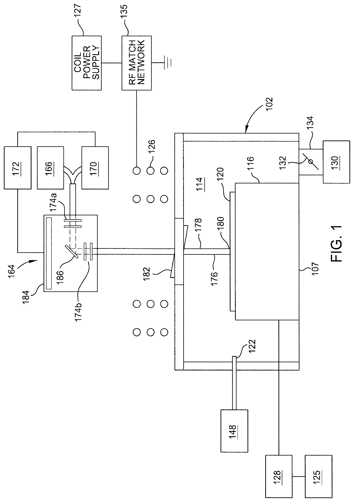
[0023]FIG. 1 is a schematic cross sectional view of a plasma processing chamber 100 in accordance with one embodiment of the present disclosure. Suitable processing chambers include inductively coupled plasma etch chambers such as the TETRA® photomask etch system and the AdvantEdge® etch system, both available from Applied Materials, Inc., of Santa Clara, Calif., among others. Other types of processing chambers may be adapted to benefit from the invention, ...


PUM


Abstract

A tilted window for use in an endpoint detection system of a processing chamber, and a processing chamber having the same are described herein. In one example, the tilted window includes a mounting frame, and a panel mounted in the mounting frame. The mounting frame has a body having a top surface, a bottom surface, and an inner edge connecting the top surface to the bottom surface of the body of the mounting frame. The mounting frame further has a panel disposed in the mounting frame. The panel has a body having a top surface and a bottom surface. The top surface of the body of the panel is oriented at acute angle relative to the top surface of the body of the mounting frame.

Description

BACKGROUNDField[0001]Embodiments of the present disclosure generally relate to etching semiconductor substrates, and more particularly, to a transparent chamber window for use in an endpoint detection system having reduced reflections of incident and reflected light.Description of the Related Art[0002]Semiconductor device geometries have dramatically decreased in size since such devices were first introduced several decades ago. The increasing circuit densities have placed additional demands on processes used to fabricate semi-conductor devices. For example, as circuit densities increase, the widths of vias, contacts and other features, as well as the dielectric materials between them, decrease to sub-micron dimensions, whereas the thickness of the dielectric layers remains substantially constant, with the result that the aspect ratios for the features, i.e., their height divided by width, increases. Reliable formation of high aspect ratio features is important to the success of sub...

Claims


Application Information

Patent Timeline
IPC IPC(8): H01J37/32H01L21/67H01L21/3065H01L21/66
CPCH01J37/32715H01J37/32458H01L21/67253H01L21/67069H01L21/3065H01L22/26H01J37/32963
Inventor LIAN, LEIHAN, PENGYU
Owner APPLIED MATERIALS INC
Learn More