Substrate cleaning device and substrate cleaning method

Active Publication Date: 2020-01-09
EBARA CORP
View PDF0 Cites 0 Cited by
  • Summary
  • Abstract
  • Description
  • Claims
  • Application Information

AI Technical Summary

Benefits of technology

The present invention is related to a substrate cleaning device and method for improving accuracy of a pressing load during cleaning. The device includes a cleaning member, a member rotation unit, a member drive unit, a load measurement unit, and a control unit. The control unit repeats an operation of comparing the measurement value of the load measurement unit with a setting load, adjusting the pressing amount of the cleaning member by a movement amount, and repeating this process until the difference value between the measurement value and the setting load becomes equal to or smaller than a threshold value. This invention improves the accuracy of the pressing load on the substrate during cleaning.

Problems solved by technology

For this reason, when the surface of substrate is not sufficiently cleaned, such as when the surface of the substrate is complicated and cleaning is difficult, leaks and adhesion defects occur due to an influence of the residue and the like, which may result in a decrease in reliability.

Method used


Image

  • Substrate cleaning device and substrate cleaning method
  • Substrate cleaning device and substrate cleaning method
  • Substrate cleaning device and substrate cleaning method

Examples


first embodiment

Substrate Cleaning Device

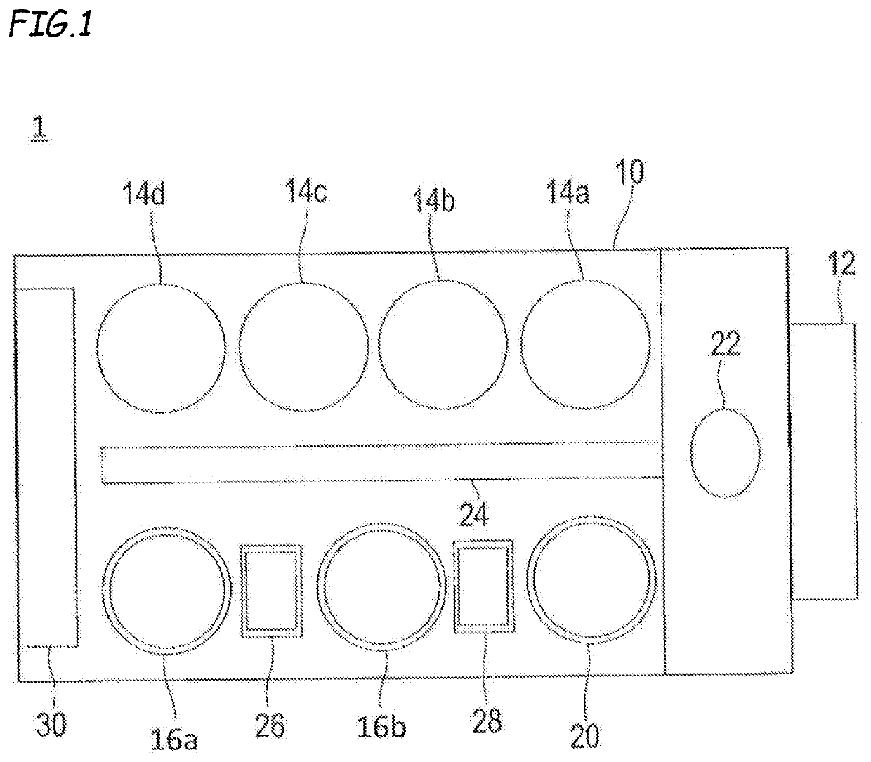
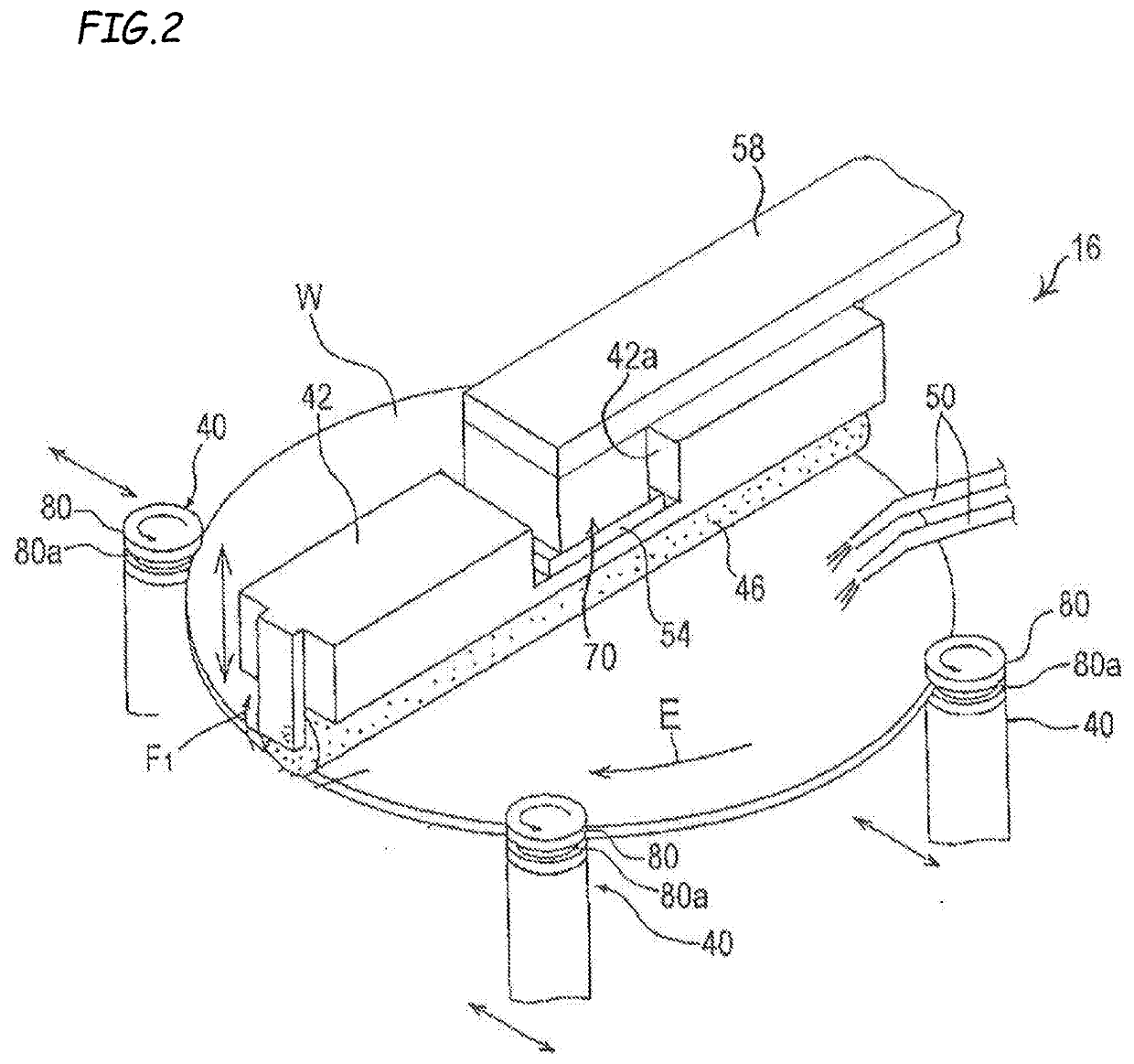
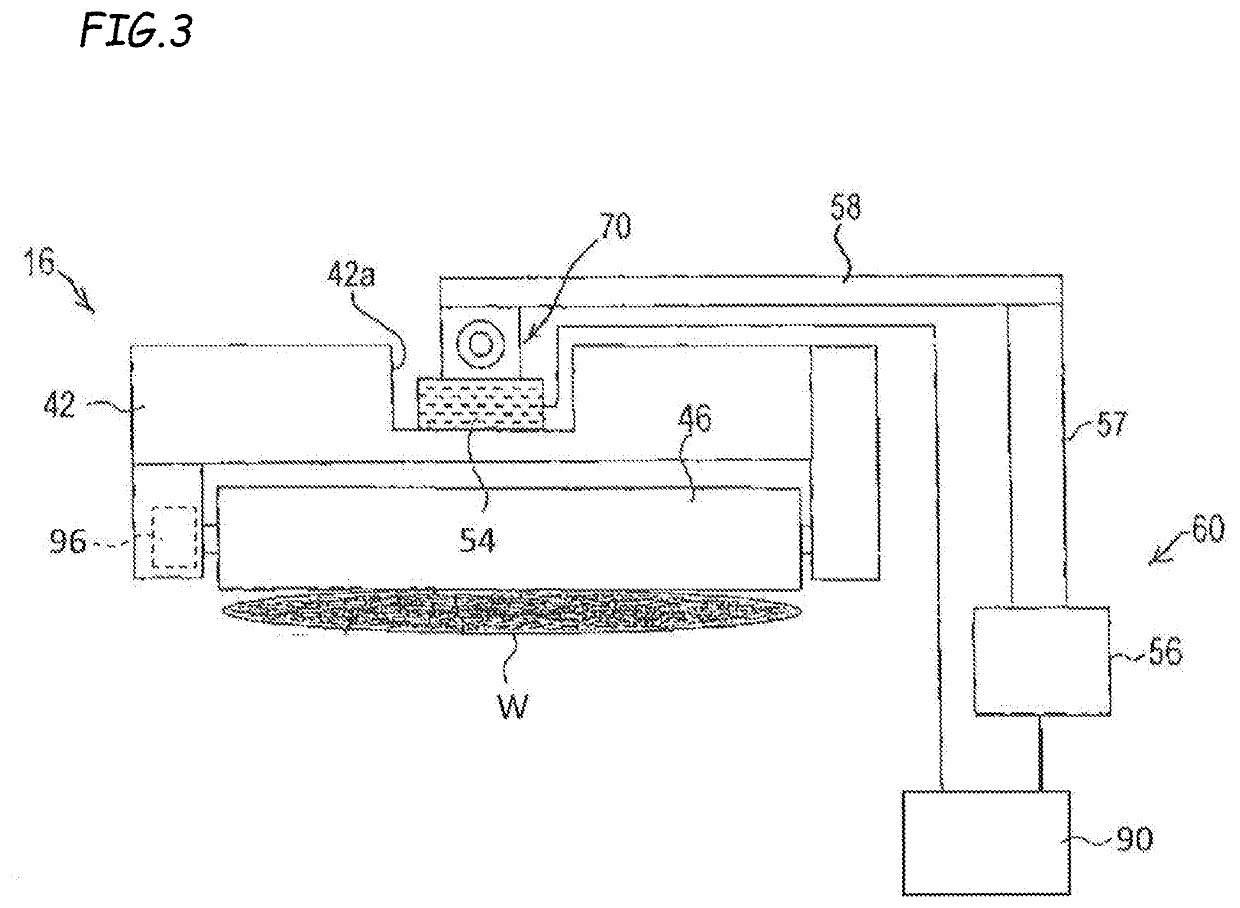
[0055]Next, a substrate cleaning device 16 according to the first embodiment will be described. FIG. 2 is a perspective view showing the substrate cleaning device 16 according to the first embodiment and FIG. 3 is a diagram showing a schematic configuration of the substrate cleaning device 16 according to the first embodiment. The substrate cleaning device 16 according to the first embodiment may be used as the first substrate cleaning device 16a and / or the second substrate cleaning device 16b in the substrate processing apparatus 1 described above.

[0056]As shown in FIGS. 2 and 3, the substrate cleaning device 16 has a cleaning member 46 that cleans a substrate W by contacting the substrate W, a member rotation unit 96 that rotates the cleaning member 46, a member drive unit 56 that presses the cleaning member 46 against the substrate W, a load measurement unit 54 that measures a pressing load of the cleaning member 46, and a control unit 90 that controls a ...

second embodiment

Substrate Cleaning Device

[0091]Next, a substrate cleaning device 16′ according to a second embodiment will be described. FIG. 8 is a perspective view showing the substrate cleaning device 16′ according to the second embodiment and FIG. 9 is a diagram showing a schematic configuration of the substrate cleaning device 16′ according to the second embodiment. The substrate cleaning device 16′ according to the second embodiment may be used as a first substrate cleaning device 16a and / or a second substrate cleaning device 16b in the substrate processing apparatus 1 described above.

[0092]As shown in FIGS. 8 and 9, in addition to a configuration of a substrate cleaning device 16 according to the first embodiment described above, the substrate cleaning device 16′ according to the second embodiment further has a second cleaning member 48 that cleans a second surface of a substrate W by contacting the second surface of the substrate W, a second member rotation unit 98 that rotates the second c...


PUM


Abstract

A substrate cleaning device includes: a pressing member that cleans a substrate by contacting the substrate; a load measurement unit that measures a pressing load of the cleaning member; and a control unit that repeats an operation of comparing the measurement value of the load measurement unit with the setting load, changing the pressing amount of the cleaning member by a first movement amount so that a difference value decreases, when the difference value is larger than a first threshold value and equal to or smaller than a second threshold value, and changing the pressing amount of the cleaning member by a second movement amount larger than the first movement amount so that the difference value decreases, when the difference value is larger than the second threshold value, until the difference value becomes equal to or smaller than the first threshold value.

Description

CROSS-REFERENCE TO RELATED APPLICATIONS[0001]This application claims the benefit of Japanese Priority Patent Application JP 2018-129086 filed on Jul. 6, 2018, the entire contents of which are incorporated herein by reference.FIELD[0002]The present technology relates to a substrate cleaning device and a substrate cleaning method.BACKGROUND AND SUMMARY[0003]At the present time, with the miniaturization of a semiconductor device, processing of a substrate having a fine structure (a substrate on which various material films having different physical properties are formed) is performed. For example, in a damascene wiring formation step of filling a wiring groove formed in the substrate with a metal, the excess metal is polished and removed by a substrate polishing device (CMP device) after damascene wiring formation, and the various material films (a metal film, a barrier film, an insulating film, and the like) having the different physical properties are formed on a surface of the subst...

Claims


Application Information

Patent Timeline
IPC IPC(8): H01L21/67B08B1/04B08B1/00H01L21/02B24B37/34B24B37/04
CPCB24B37/34B08B1/003H01L21/67046H01L21/67219B08B1/006B24B37/04B08B1/04H01L21/02096H01L21/67253B08B3/022B08B2203/0217B08B1/20H01L21/67051H01L21/67028H01L21/68764H01L21/67259H01L21/02052H01L21/02057H01L21/304B08B1/32B08B1/143B08B1/145
Inventor XU, HAIYANGINABA, MITSUHIKO
Owner EBARA CORP
Why Eureka
Try Eureka