Connector

a technology of connecting rods and connectors, applied in the direction of coupling devices, two-part coupling devices, electrical apparatus, etc., can solve problems such as unstable operation, and achieve the effects of improving operability, reducing operation space, and good workability

Active Publication Date: 2020-01-09
YAZAKI CORP
View PDF6 Cites 4 Cited by
  • Summary
  • Abstract
  • Description
  • Claims
  • Application Information

AI Technical Summary

Benefits of technology

[0024]According to the connector having the configuration (4), in a state in which the slide member is not mounted to the first housing, the transmission gear member is held at the initial position by the locking of the pair of gear locking portions. Therefore, when the slide member is mounted to the first housing, the first rack gear portion, and the driven gear portion of the transmission gear member can be reliably engaged with each other. In addition, the locking of the pair of gear locking portions for holding the transmission gear member at the initial position is released as the slide member is mounted to the first housing, so that the workability is good.
[0025]According to the present invention, it is possible to provide a connector capable of reducing the operation space and improving the operability by equalizing the boosting effects at the time of fitting and separation.

Problems solved by technology

Therefore, boosting effects are different at the time of fitting and separation, and an operability is unstable.

Method used


Image

  • Connector
  • Connector
  • Connector

Examples


Embodiment Construction

[0038]Hereinafter, an embodiment of the present invention will be described with reference to the drawings.

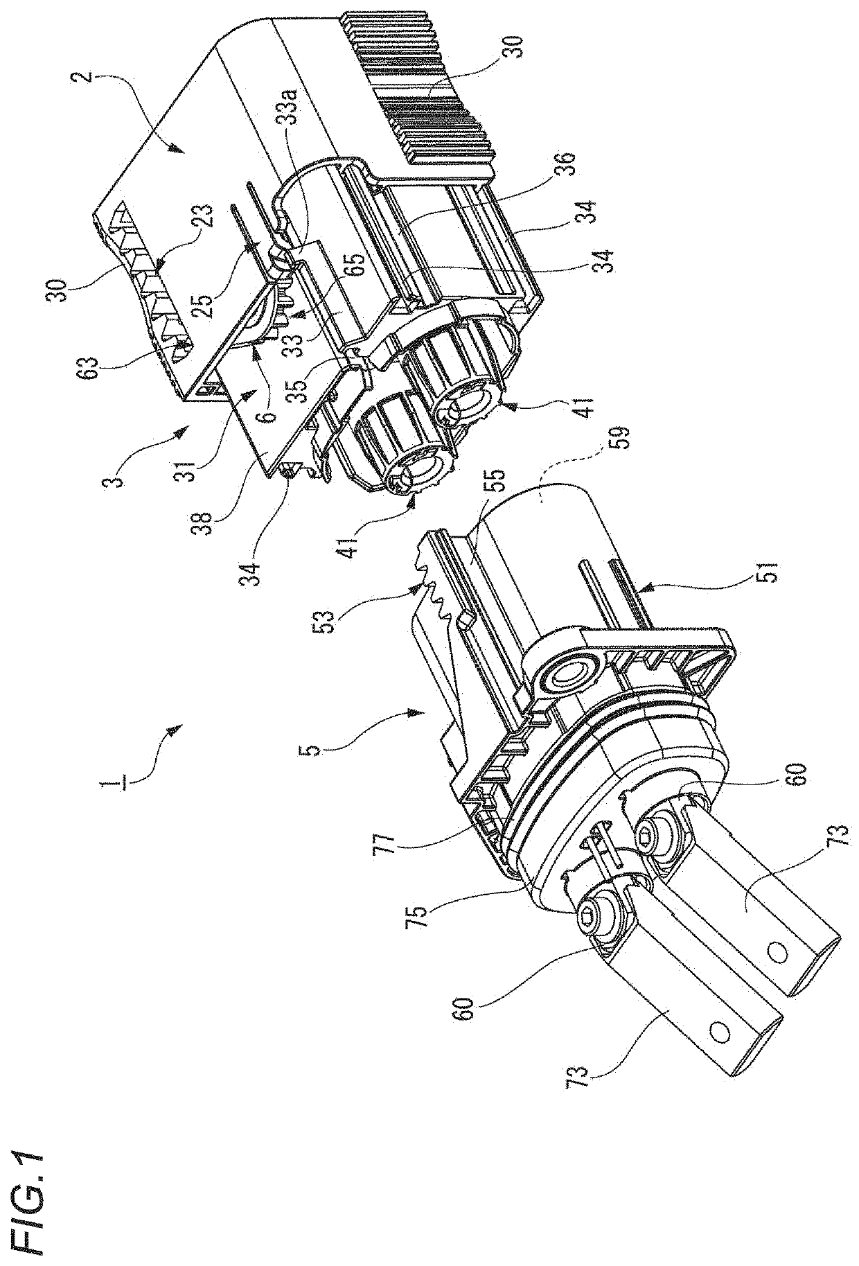
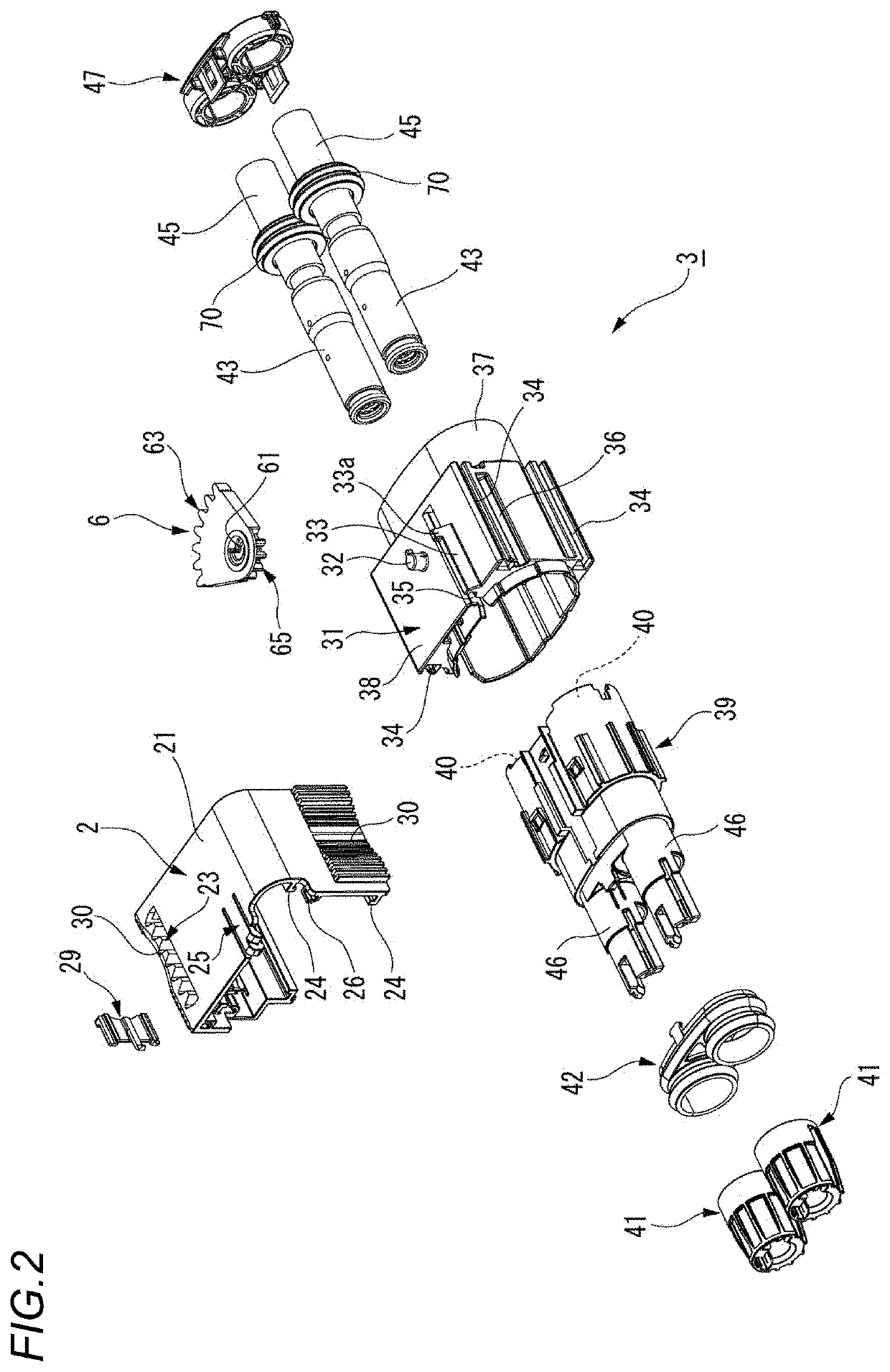
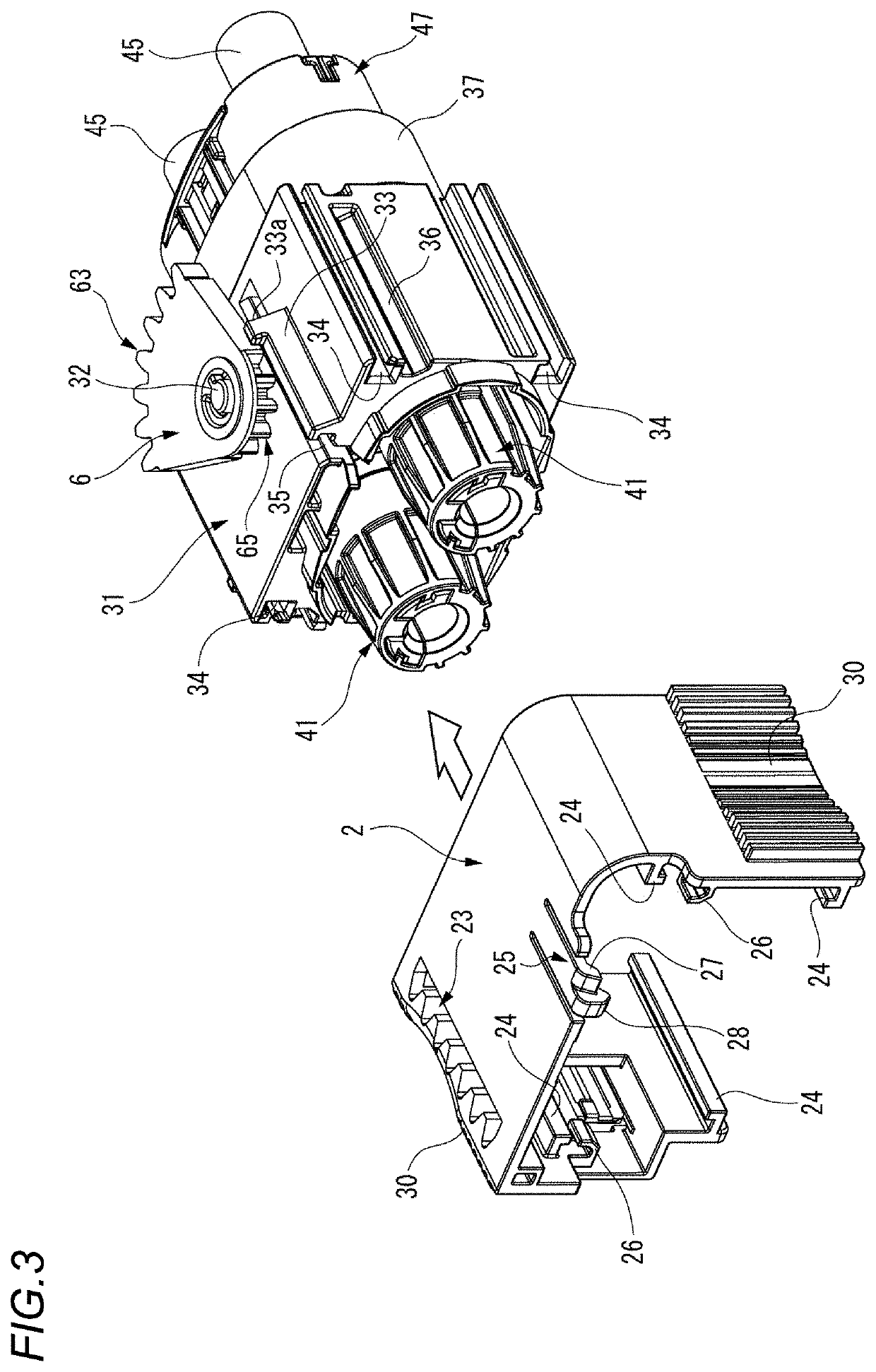
[0039]FIG. 1 is a perspective view showing a first housing 3 and a second housing 5 configuring a connector 1 according to a first embodiment of the present invention. FIG. 2 is an exploded perspective view of the first housing 3 shown in FIG. 1. FIG. 3 is a perspective view of a state in which a slide member 2 is removed from the first housing 3. FIG. 4 is a back view of the connector 1 shown in FIG. 1.

[0040]As shown in FIGS. 1 and 2, the connector 1 according to the first embodiment includes the first housing 3, the second housing 5, the slide member 2 movable relative to the first housing 3 along a connector fitting direction, a transmission gear member 6 rotatably pivoted by a support shaft 32 of the first housing 3, a first rack gear portion 23 provided on the slide member 2, and a second rack gear portion 53 provided on the second housing 5.

[0041]The first housing 3 and t...


PUM


Abstract

A connector includes a second housing fittable with a first housing, a slide member movable relative to the first housing along a connector fitting direction, a transmission gear member rotatably supported by a support shaft provided on the first housing, a first rack gear portion provided on the slide member along the connector fitting direction, a driven gear portion of the transmission gear member rotated by movement of the first rack gear portion in the connector fitting direction, a main drive gear portion of the transmission gear member provided on a side opposite to the driven gear portion with the support shaft interposed therebetween, and a second rack gear portion provided on the second housing along the connector fitting direction, and movable relative to the first housing along the connector fitting direction by rotation of the main drive gear portion.

Description

CROSS-REFERENCE TO RELATED APPLICATIONS[0001]This application is based on and claims priority under 35 USC 119 from Japanese Patent Application No. 2018-129121 filed on Jul. 6, 2018, the contents of which are incorporated herein by reference.TECHNICAL FIELD[0002]The present invention relates to a connector.BACKGROUND ART[0003]As shown in FIG. 10, there has been known a lever-type connector 501 in which a lever 550 is rotatably attached to a first housing 510, the first housing 510 is shallowly fitted to a second housing 530, a cam follower 531 of the second housing 530 is made to enter an inlet of a cam groove 551 of the lever 550, and the two housings 510, 530 are fitted together due to a boosting action by rotating the lever 550 from this state to engage a track portion of the cam groove 551 with the cam follower 531 (see Patent Document 1).[0004]However, in the lever-type connector 501, since an operation portion of the lever 550 moves in a peripheral direction around the first h...

Claims


Application Information

Patent Timeline
Patent Type & Authority Applications(United States)
IPC IPC(8): H01R13/629H01R13/627
CPCH01R13/62938H01R13/6275H01R13/62944H01R13/62955H01R13/6295H01R13/62977H01R24/005H01R13/707H01R2201/26
Inventor AOSHIMA, KENGOMURAKAMI, TAKAO
Owner YAZAKI CORP
Why Eureka
Try Eureka