Range-finding and compensating scope with ballistic effect compensating reticle, aim compensation method and adaptive method for compensating for variations in ammunition or variations in atmospheric conditions

Active Publication Date: 2020-01-16
TUBB G DAVID
View PDF6 Cites 11 Cited by
  • Summary
  • Abstract
  • Description
  • Claims
  • Application Information

AI Technical Summary

Benefits of technology

[0044]Accordingly, it is an object of the present invention to overcome the above mentioned difficulties by providing an enhanced system and method for sensing or measuring the range to a selected target and then compensating for a projectile's ballistic behavior while developing a field expedient firing solution, and calculating and displaying a correct point

Problems solved by technology

The variations in the anomalies were observed to be repeatable, and so a precise evaluation of the anomalies was undertaken and it was dis

Method used


Image

  • Range-finding and compensating scope with ballistic effect compensating reticle, aim compensation method and adaptive method for compensating for variations in ammunition or variations in atmospheric conditions
  • Range-finding and compensating scope with ballistic effect compensating reticle, aim compensation method and adaptive method for compensating for variations in ammunition or variations in atmospheric conditions
  • Range-finding and compensating scope with ballistic effect compensating reticle, aim compensation method and adaptive method for compensating for variations in ammunition or variations in atmospheric conditions

Examples


Embodiment Construction

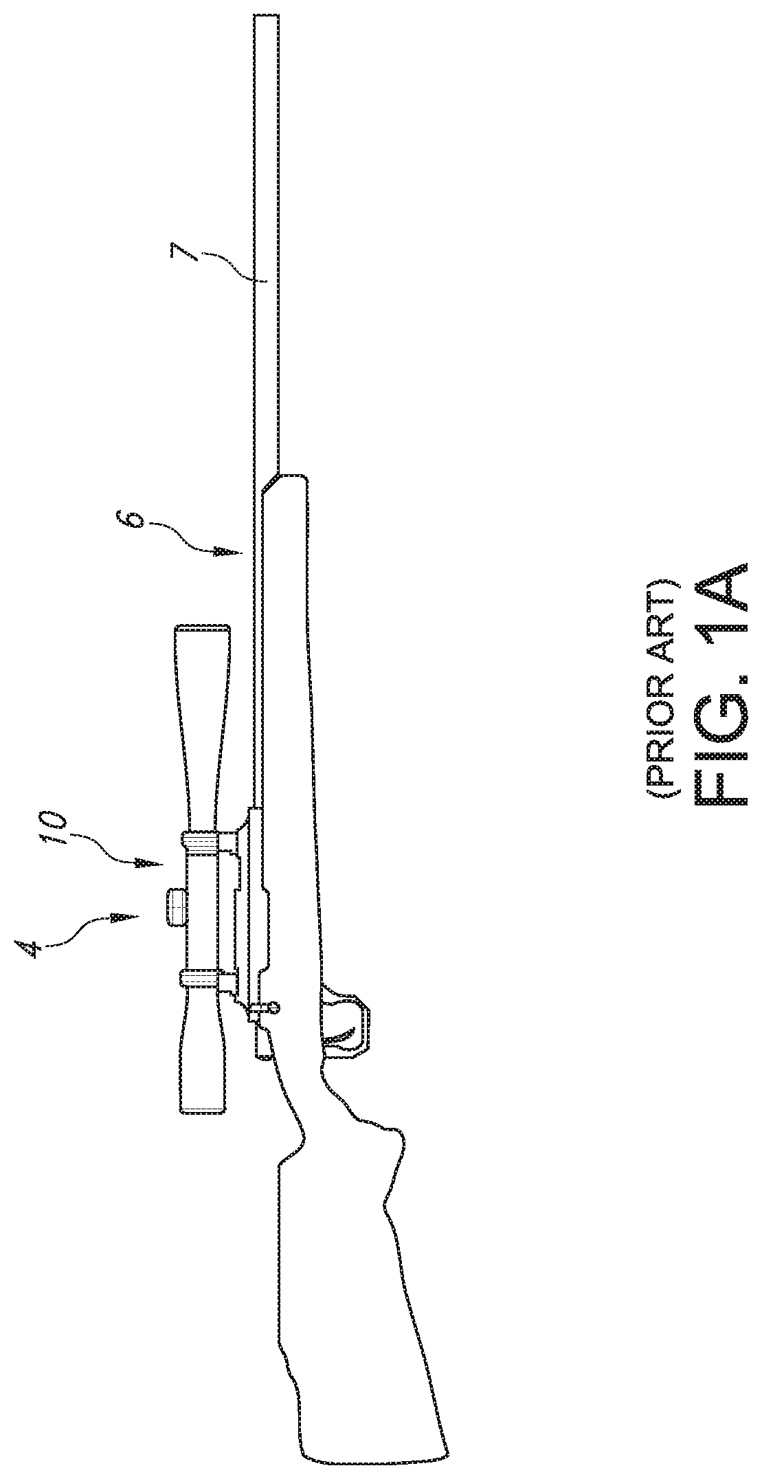
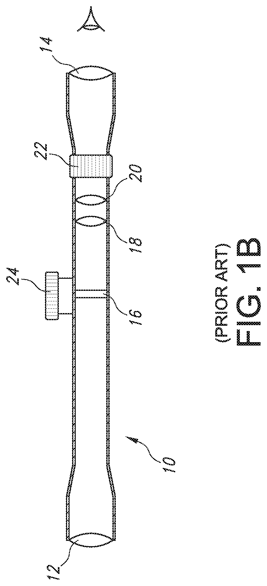
[0079]In order to provide context for the present invention, please refer again to Prior Art FIGS. 1A-1M. FIG. 1A's projectile weapon system 4 including a rifle 6 with a barrel 7 and a telescopic rifle sight or projectile weapon aiming system 10 are illustrated in the standard configuration where the rifle's barrel 7 terminates distally in an open lumen or muzzle and rifle scope 10 is mounted upon rifle 6 in a configuration which allows the rifle system 4 to be adjusted such that a user or shooter sees a Point of Aim (“POA”) in substantial alignment with the rifle's Center of Impact (“COI”) when shooting or firing selected ammunition (not shown) at a selected target (e.g., 28). FIG. 1B schematically illustrates exemplary internal components for telescopic rifle sight or projectile weapon aiming system 10. As noted above, rifle scope 10 generally includes a distal objective lens 12 aligned with a proximal ocular or eyepiece lens 14 at the ends of a rigid and substantially tubular bod...


PUM


Abstract

A range-finding and ballistics effect compensating scope 804 with a ballistic effect compensating reticle aim point field 650 and ammunition adaptive aim compensation method for rifle sights or projectile weapon aiming systems includes (a) a primary aiming point 658 adapted to be sighted-in at a first selected range and (b) the locus of the RF beam for sensing range 29 to a selected target 28. The when firing, the reticle's aim point field also includes a sloped array of wind dots (e.g., 660) illustrating aim points for a range of crosswind conditions. The method for compensating for a projectile's ballistic behavior permits the shooter to sense or measure the LOS range to target 29 and sense or input the slope angle 27 and local or nominal air density ballistic characteristics (e.g., air density), and then display corrected hold points.

Description

PRIORITY CLAIMS AND CROSS-REFERENCE TO RELATED APPLICATIONS[0001]This application is related to and claims priority from:(1) co-pending and commonly owned U.S. provisional patent application No. 62 / 650,602, filed Mar. 30, 2018,(2) and is also a continuation in part of co-pending and commonly owned U.S. non-provisional patent application Ser. No. 16 / 253,169, filed Jan. 21, 2019, which is a continuation of(3) Ser. No. 15 / 224,646 filed Jul. 31, 2016, now patented (U.S. Pat. No. 10,184,752) which claims Priority from(4) Provisional Application 62 / 274,054, filed Dec. 31, 2015, and(5) Provisional Application 62 / 199,139, filed Jul. 30, 2015,(6) and is also a continuation in part of co-pending and commonly owned U.S. non-provisional patent application Ser. No. 15 / 419,793, filed Jan. 30, 2017, which is a continuation of(7) Ser. No. 14 / 216,674, filed Mar. 17, 2014, now patented (U.S. Pat. No. 9,581,415) which is a continuation of(8) Ser. No. 13 / 947,858, filed Jul. 22, 2013, now patented (U.S....

Claims


Application Information

Patent Timeline
IPC IPC(8): F41C23/16F41A21/44
CPCF41A21/44F41C23/16F41G1/38F41G1/473F41G3/06
Inventor TUBB, G. DAVID
Owner TUBB G DAVID
Why Eureka
Try Eureka