Supercharge Your Innovation With Domain-Expert AI Agents!

Optical output system and lighting unit comprising the system

a technology of optical output system and lighting unit, which is applied in the direction of lighting and heating apparatus, semiconductor devices for light sources, instruments, etc., can solve the problems of high cost, undesired high volume/size of optical system, etc., and achieve low cost, high efficiency light output, and good light mixing

Active Publication Date: 2020-01-16
SIGNIFY HLDG BV
View PDF7 Cites 0 Cited by
  • Summary
  • Abstract
  • Description
  • Claims
  • Application Information

AI Technical Summary

Benefits of technology

This patent is about a lighting unit that produces high-quality light. The lighting unit has two arrays of lenses, which are placed close enough together that they interfere with each other. To reduce this interference, the patent suggests putting a small gap between the lenses. This improves the optical output system and makes it more efficient in producing light. The lighting unit also has a housing with reflective walls and a reflective base, which helps to create a well-controlled beam of light. Overall, this patent provides a technical solution for improving the performance and efficiency of lighting units.

Problems solved by technology

Additional optics is thus needed and this gives an optical system with an undesired high volume / size and high cost.

Method used


Image

  • Optical output system and lighting unit comprising the system
  • Optical output system and lighting unit comprising the system
  • Optical output system and lighting unit comprising the system

Examples


Embodiment Construction

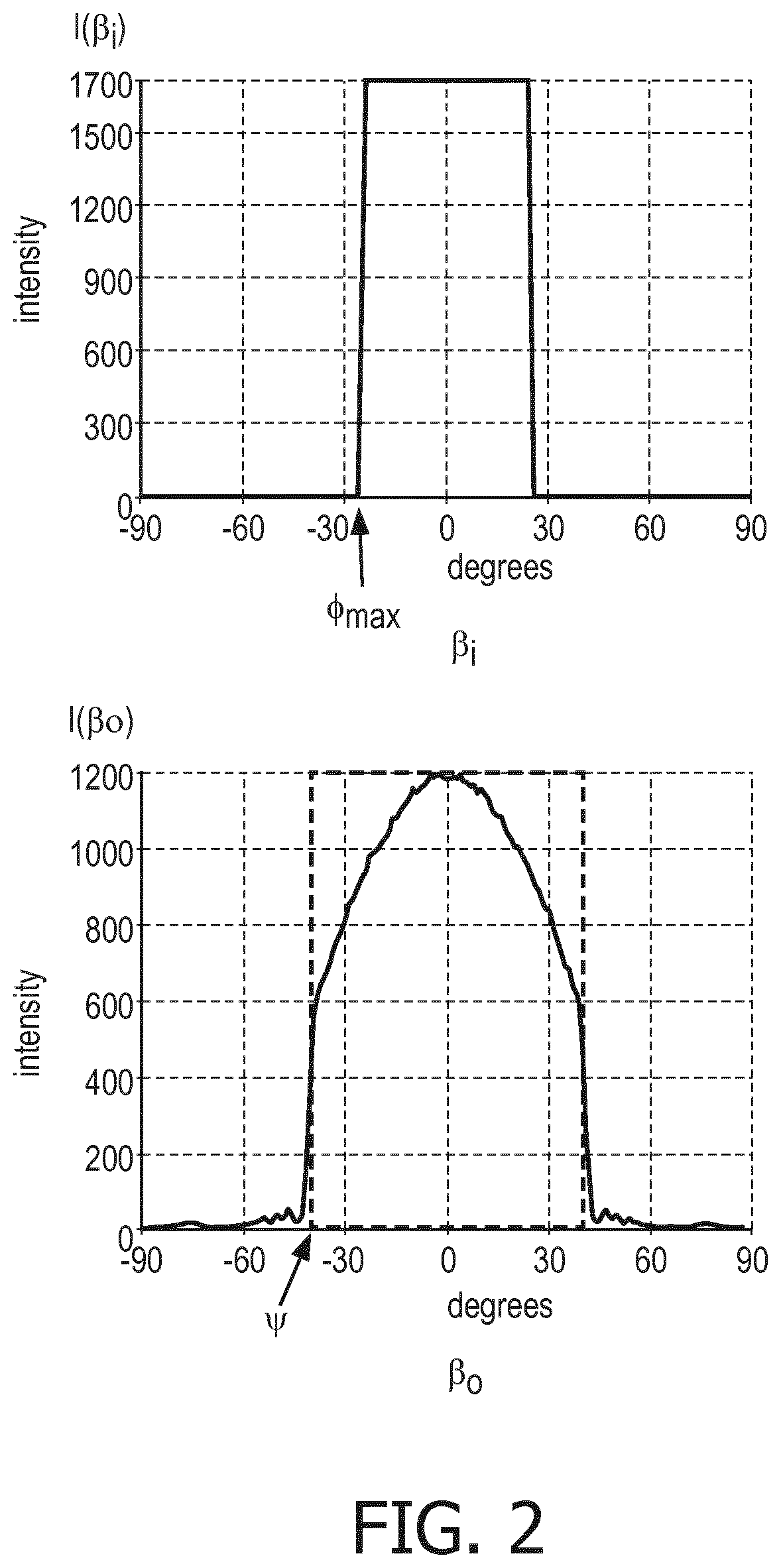
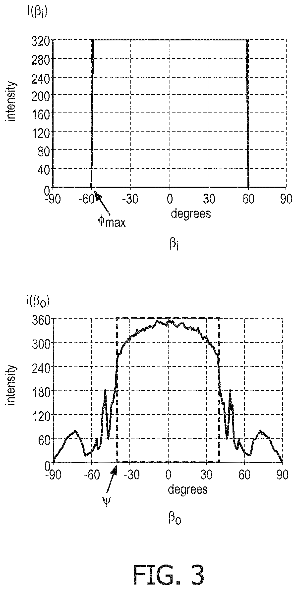
[0052]The invention provides an optical output system for an LED light source which has a pair of lens arrays with a narrow air gap between the lens arrays. The optical system provides an optical integration function for light mixing, and the air gap enables a uniform wide beam output to be provided even for incident light from a wide range of angles, for example as received from a non-collimated light source.

[0053]FIG. 4 shows an example of the output system.

[0054]A first array 40 of lenses comprises convex lenses 42 facing the incident light, namely facing a light source location. A second array 44 of lenses is on the opposite side of the first array of lenses to the light source location, and comprises convex lenses 46 facing away from the light source location. The first lens array 40 has an outer surface 40a which defines the lens shapes and an inner surface 40b which is flat. The second lens array 44 has an outer surface 44a which defines the lens shapes and an inner surface 4...


PUM

PropertyMeasurementUnit
thicknessaaaaaaaaaa
thicknessaaaaaaaaaa
thicknessaaaaaaaaaa

Abstract

An optical output system for an LED light source has a pair of lens arrays (40, 42) with a narrow air gap (48) between the lens arrays (40, 42). The optical system provides an optical integration function for light mixing, and the air gap (48) enables a uniform wide-beam output to be provided even for incident light from a wide range of angles, for example as received from a non-collimated light source.

Description

FIELD OF THE INVENTION[0001]This invention relates to an optical output system, for example for processing the output of an LED light source.BACKGROUND OF THE INVENTION[0002]LED luminaires are well known, in which an LED light source (of one or more LEDs) is provided inside a housing, and a light output panel is provided in front of the light source inside the luminaire.[0003]It is known to provide the light output panel with a profiled surface in order to prevent transmitted light from radiating in undesired directions. The light output panel is for example a plate of plastic or any other material such as polymethyl methacrylate (PMMA) or polycarbonate (PC).[0004]The purpose of the panel is to ensure that transmitted light radiates from the panel in the desired directions. Furthermore, the panel may be used to provide color mixing and to reduce image artefacts caused by the light source.[0005]One approach for providing color mixing is to make use of an array of lenslets, for exampl...

Claims


Application Information

Patent Timeline
Patent Type & Authority Applications(United States)
IPC IPC(8): G02B3/00G02B19/00H01L33/58F21V5/00F21V5/04
CPCG02B19/0061G02B3/0062H01L33/58G02B3/0056F21V5/004F21V5/04G02B19/0014F21Y2115/10
Inventor BOONEKAMP, ERIK PAUL
Owner SIGNIFY HLDG BV
Features
  • R&D
  • Intellectual Property
  • Life Sciences
  • Materials
  • Tech Scout
  • Unparalleled Data Quality
  • Higher Quality Content
  • 60% Fewer Hallucinations
Learn More