Electromagnetic rotary drive and a rotational device

a technology of rotating drive and rotor, which is applied in the direction of magnetic holding device, magnetic circuit rotating parts, magnetic circuit shape/form/construction, etc., can solve the problems of reducing passive magnetic stabilization against tilting, no longer sufficient to ensure safe and trouble-free operation of rotary drive, etc., to improve the stabilization of the rotor, increase the tilting rigidity of the rotor, and improve the effect of the stability of the rotor

Active Publication Date: 2020-01-16
LEVITRONIX
View PDF0 Cites 7 Cited by
  • Summary
  • Abstract
  • Description
  • Claims
  • Application Information

AI Technical Summary

Benefits of technology

[0022]Due to the interaction of the additional bearing stator, more precisely the magnetically effective stator ring of the additional bearing stator, with the magnetically effective bearing ring of the rotor, a significantly improved stabilization of the rotor against tilting with respect to the radial plane can be achieved in particular, wherein the radial plane is that plane in which the radial position of the rotor is actively magnetically regulated. The additional bearing stator and the bearing ring of the rotor function in principle like an additional passive magnetic axial bearing of the rotor, which in particular significantly increases the tilting rigidity of the rotor. The maximum torque that causes tilts of the rotor, which can be compensated with the design according to the invention, is considerably larger than with known electromagnetic rotary drives which are designed as external rotors with a magnetically levitated, disk-shaped or ring-shaped magnetically effective rotor core, for example by at least a factor of 20. Due to this fact, the rotary drive according to the invention can be used for applications for which known designs are not suitable or not suitable at

Problems solved by technology

Such single-use applications today frequently replace processes in which all those components which come into contact with the substances to be treated in the process once had to be cleaned and sterilized in a complex manner, for example by steam sterilization, due to the very high purity demands.
However, it has been shown in particular in designs as external rotor that for

Method used


Image

  • Electromagnetic rotary drive and a rotational device
  • Electromagnetic rotary drive and a rotational device
  • Electromagnetic rotary drive and a rotational device

Examples


first embodiment

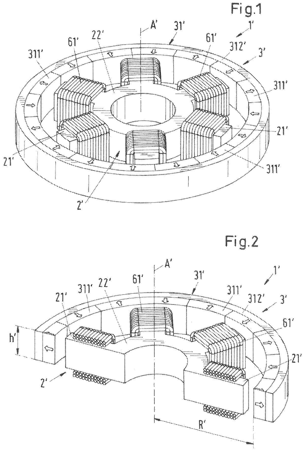
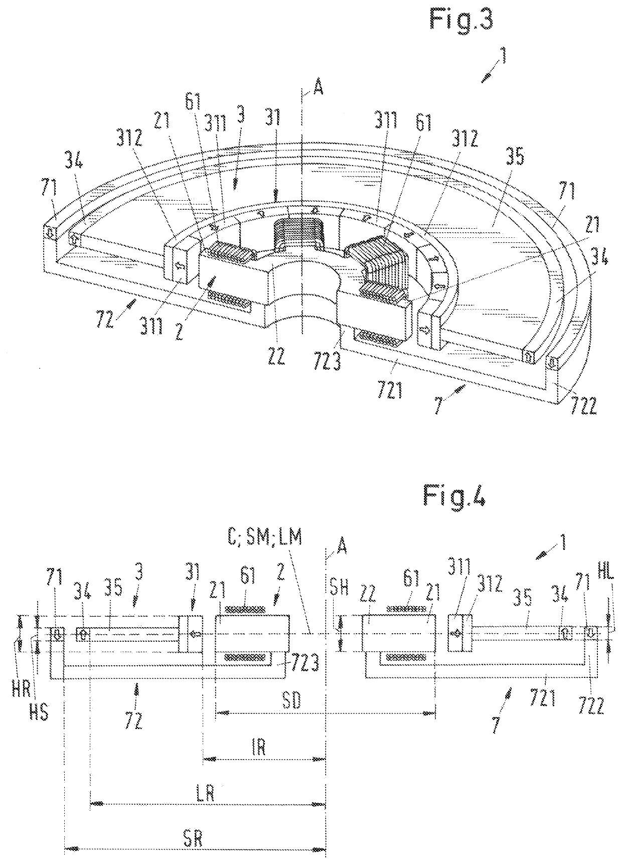
[0097]In order to significantly improve the passive magnetic stabilization of the rotor 3, in particular against tilting, an additional bearing stator 7 is provided according to the present invention, which interacts with a magnetically effective bearing ring 34 of the rotor 3. This will be explained in more detail below with reference to the

[0098]The rotor 3 comprises the magnetically effective bearing ring 34 being arranged externally disposed and spaced from the magnetically effective core 31 of the rotor 3. The bearing ring 34 is designed as a permanent magnetic ring with an inner radius LR, the ring being magnetized in axial direction A, as represented in the axial direction A upwards (FIG. 3 and FIG. 4). The magnetization of the bearing ring 34 is indicated by the arrows without a reference sign (in the bearing ring 34). The bearing ring 34 can be designed as a permanent magnetic ring in one piece, or segmented, i.e. composed of a plurality of ring-segment-shaped permanent mag...

second embodiment

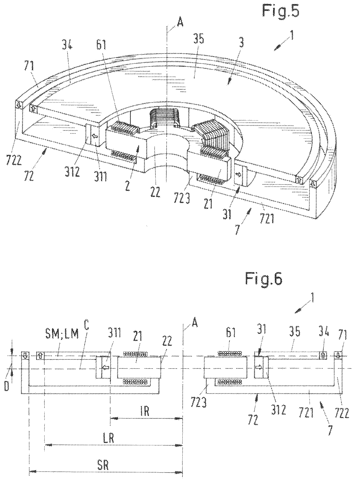
[0129]FIG. 9 shows in a perspective sectional representation a variant of the second embodiment in a representation corresponding to FIG. 7. For a better understanding, FIG. 10 still shows a schematic section in axial direction through this variant.

[0130]In the variant of the second embodiment represented in FIG. 9 and FIG. 10, the bearing ring 34 of the rotor 3 is arranged with respect to the axial direction A at a distance D different from zero to the magnetic central plane C of the magnetically effective core 31 of the rotor 3. This means that the bearing ring 34 is arranged such that the geometric central plane LM of the bearing ring 34 lies no longer in the magnetic central plane C, but that the geometric central plane LM of the bearing ring 34 is arranged parallel with the distance D to the magnetic central plane C. According to the representation (FIG. 9, FIG. 10), the bearing ring 34 is arranged below the ring-shaped magnetically effective core 31. It is understood that the ...


PUM


Abstract

An electromagnetic rotary drive includes a ring-shaped magnetically effective core arranged around a stator and has a magnetic central plane. The stator is a bearing and a drive stator, with which, the rotor is contactlessly magnetically drivable about an axis of rotation, and with which the rotor is contactlessly magnetically levitatable with respect to the stator. The rotor actively magnetically levitated in a radial plane perpendicular to an axial direction, and passively magnetically stabilized in the axial direction and against tilting. The rotor includes a magnetically effective bearing ring arranged radially externally disposed and spaced from the magnetically effective core, and a bearing stator having a magnetically effective stator ring interacts with the bearing ring. The bearing stator is configured such that the stator ring passively magnetically stabilizes the rotor against tilting, and the bearing ring is connected to the magnetically effective core of the rotor via a connecting element.

Description

CROSS-REFERENCE TO RELATED APPLICATION[0001]This application claims priority to European Application No. 18183186.8, filed Jul. 12, 2018, the contents of which are hereby incorporated herein by reference.BACKGROUNDField of the Invention[0002]The invention relates to an electromagnetic rotary drive and to a rotational device.BACKGROUND OF THE INVENTION[0003]Conventional electromagnetic rotary drives are generally designed and operated according to the principle of a bearingless motor. The term bearingless motor in this respect means an electromagnetic rotary drive in which the rotor is levitated completely magnetically with respect to the stator, with no separate magnetic bearings provided. For this purpose, the stator is designed as a bearing and drive stator, which is therefore both the stator of the electric drive and the stator of the magnetic levitation. By using the electrical windings of the stator, a rotating magnetic field can be generated which, on the one hand, exerts a to...

Claims


Application Information

Patent Timeline
IPC IPC(8): H02K7/09F16C32/04H02K21/14
CPCH02K2201/15F16C32/0497H02K21/14H02K7/09H02N15/00H02K1/2791H02K1/28H02K7/14F16C32/048B01F33/4535F16C32/0493H02K2213/03F16C2380/26H02K1/2786
Inventor NUSSBAUMER, THOMASHOLENSTEIN, THOMAS
Owner LEVITRONIX
Why Eureka
Try Eureka