Check patentability & draft patents in minutes with Patsnap Eureka AI!

Comparator circuit with feedback and method of operation

a comparator circuit and feedback technology, applied in the field of integrated circuits, can solve the problems of device or system on the chip (soc) more vulnerable, voltage is altered, and damage can result to the so

Active Publication Date: 2020-01-16
NXP USA INC
View PDF1 Cites 1 Cited by
  • Summary
  • Abstract
  • Description
  • Claims
  • Application Information

AI Technical Summary

Benefits of technology

The present invention relates to a comparator circuit with feedback that can detect supply voltage incompatibilities and alert the user or customer. The comparator circuit is designed to compare two input voltages and alert when the two voltages are close to the comparator's supply voltage. This is important because it allows for early detection of supply voltage tampering or incompatibility events, which can lead to malicious attacks on the system. The comparator circuit is low power and can remain on, making it ideal for use in SoCs. It can also be used to detect supply voltage incompatibility for an entire pad segment. The invention provides a solution for ensuring the reliability and security of integrated circuits.

Problems solved by technology

In System on Chips (SoCs), it is important that the supply voltages provided to the SoC be compatible with the SoC, because otherwise, damage can result to the SoC.
Also, during some hacking events, the supply voltage is altered in order to make a device or System on Chip (SoC) more vulnerable.
For example, fault injection attacks are commonly performed by tampering with the supply voltage in order to maliciously alter software execution.
However, using a traditional comparator which compares two input voltages, it is difficult to compare the two voltages when either or both voltages are equal to or higher than the comparator supply voltage.
Therefore, these traditional comparators are not reliable for comparisons in which two inputs are close to the supply.
Furthermore, such comparators need to operate at low power since they should always be on.

Method used


Image

  • Comparator circuit with feedback and method of operation
  • Comparator circuit with feedback and method of operation
  • Comparator circuit with feedback and method of operation

Examples


Embodiment Construction

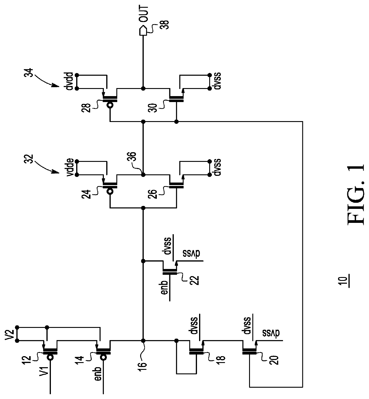
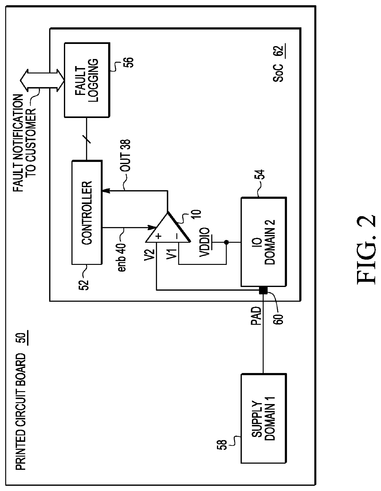
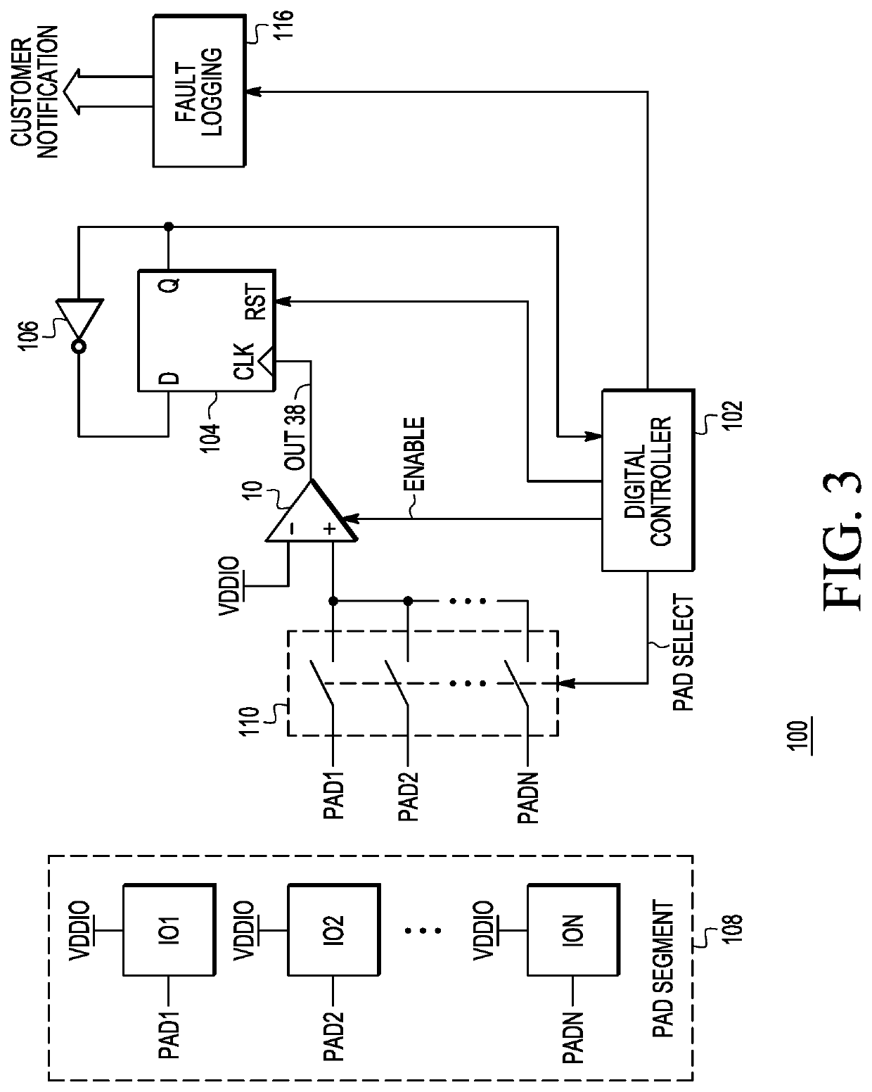
[0008]In one aspect, a low power coarse comparator compares two direct-current (DC) voltage levels. This comparator may be used, for example, to detect an over voltage situation. This comparator consumes negligible DC current due to a feedback mechanism that automatically disables the comparator when the output switches. In this manner, the comparator consumes low power and can remain on. The comparator circuit can be used to detect a supply voltage tampering or incompatibility event and assert a fault indicator in response thereto. Furthermore, such a comparator circuit, along with a digital controller, can be used to detect supply voltage incompatibility for an entire pad segment.

[0009]FIG. 1 illustrates, in schematic form, a comparator circuit 10 in accordance with one embodiment of the present invention. Comparator circuit 10 includes P-channel transistors 12, 14, 24, and 28 and N-channel transistors 18, 20, 22, 26, and 30. A control electrode of transistor 12 is coupled to rece...


PUM


Abstract

A comparator circuit includes a first transistor have a control electrode coupled to a first input voltage, a first current electrode coupled to a second input voltage, and a second current electrode coupled to a first circuit node. The circuit also includes a first inverter coupled to a first voltage supply terminal and having a first input coupled to the first circuit node and an output, a second transistor having a control electrode coupled to the output of the first inverter, and an active resistive element coupled in series between the first circuit node and a first current electrode of the second transistor.

Description

BACKGROUNDField[0001]This disclosure relates generally to integrated circuits, and more specifically, to a comparator circuit with feedback.Related Art[0002]In System on Chips (SoCs), it is important that the supply voltages provided to the SoC be compatible with the SoC, because otherwise, damage can result to the SoC. Therefore, it is desirable to alert a user or customer when supply voltage incompatibilities occur. Also, during some hacking events, the supply voltage is altered in order to make a device or System on Chip (SoC) more vulnerable. For example, fault injection attacks are commonly performed by tampering with the supply voltage in order to maliciously alter software execution. Therefore, it is useful, for safety and security purposes, to have a comparator able to detect such variations in the supply voltage. However, using a traditional comparator which compares two input voltages, it is difficult to compare the two voltages when either or both voltages are equal to or...

Claims


Application Information

Patent Timeline
Patent Type & Authority Applications(United States)
IPC IPC(8): H03K5/24H03K3/037G01R31/40
CPCH03K5/24G01R31/40H03K19/20H03K3/037G01R19/16547G01R19/16576G06F1/28H03K5/2472
Inventor MICIELLI, CHRISTOPHER JAMESJAGANNATHAN, SRIKANTHRANA, MANMOHANCULSHAW, CARL
Owner NXP USA INC
Features
  • R&D
  • Intellectual Property
  • Life Sciences
  • Materials
  • Tech Scout
  • Unparalleled Data Quality
  • Higher Quality Content
  • 60% Fewer Hallucinations
Learn More