Magnetic field measurement system and method of using variable dynamic range optical magnetometers

a variable dynamic range, optical magnetometer technology, applied in the direction of magnetic measurement, magnetic offset compensation, instruments, etc., can solve the problems of reducing reducing the dynamic range of the detector array, and unable to use the serf magnetometer to measure the earth's surface, etc., to reduce the dynamic range of the detector array, and increase the sensitivity of the detector array

Active Publication Date: 2020-01-23
HI LLC
View PDF0 Cites 62 Cited by
  • Summary
  • Abstract
  • Description
  • Claims
  • Application Information

AI Technical Summary

Benefits of technology

[0007]In at least some embodiments, the processor is configured to increase the dynamic range of the array of magnetometers by adjusting the spatial variation of the compensation field to decrease the number of the magnetometers of the array operating in the measurement mode. In at least some embodiments, the processor is configured to decrease the dynamic range of the array of magnetometers by adjusting the spatial variation of the compensation field to increase the number of the magnetometers of the array operating in the measurement mode.
[0008]In at least some embodiments, the processor is configured to increase the sensitivity of the array of magnetometers by adjusting the spatial variation of the compensation field to increase the number of the magnetometers of the array operating in the measurement mode. In at least some embodiments, the processor is configured to decrease the sensitivity of the array of magnetometers by adjusting the spatial variation of the compensation field to decrease the number of the magnetometers of the array operating in the measurement mode.
[0012]In at least some embodiments, the processor is configured to increase the dynamic range of the detector array by adjusting the spatial variation of the compensation field to decrease the number of the domains operating in the measurement mode. In at least some embodiments, the processor is configured to decrease the dynamic range of the detector array by adjusting the spatial variation of the compensation field to increase the number of the domains operating in the measurement mode.
[0013]In at least some embodiments, the processor is configured to increase the sensitivity of the detector array by adjusting the spatial variation of the compensation field to decrease the number of the domains operating in the measurement mode. In at least some embodiments, the processor is configured to decrease the sensitivity of the detector array by adjusting the spatial variation of the compensation field to increase the number of the domains operating in the measurement mode.

Problems solved by technology

However, due to the intrinsic dynamic range of zero-field resonances SERF magnetometers can typically only operate in an ambient background magnetic field environment ranging from 0 nT to a few tens of nT.
Due to its limited dynamic range, a SERF magnetometer cannot be used to measure (and therefore suppress through electromagnetic inductors) the Earth's magnetic field, which has a magnitude that varies from a few 1,000 nT to 80,000 nT depending on location.
One challenge with a SQUID detector is that it requires cryogenic cooling which can be costly and bulky.

Method used


Image

  • Magnetic field measurement system and method of using variable dynamic range optical magnetometers
  • Magnetic field measurement system and method of using variable dynamic range optical magnetometers
  • Magnetic field measurement system and method of using variable dynamic range optical magnetometers

Examples


Embodiment Construction

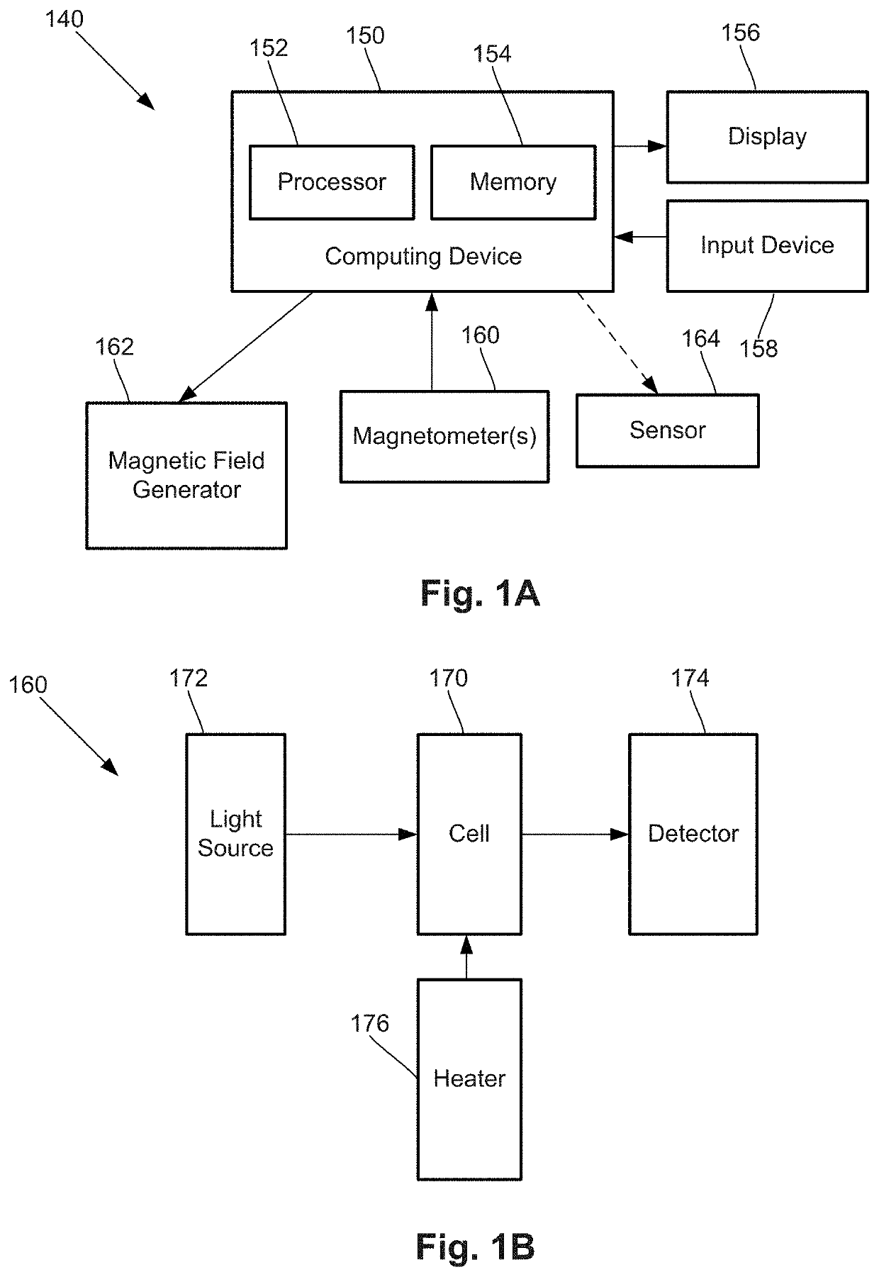
[0032]The present disclosure is directed to the area of magnetic field measurement systems using optical magnetometers. The present disclosure is also directed to magnetic field measurement systems with variable dynamic range.

[0033]A variety of different zero-field magnetometers can be used in the systems and methods described herein. These magnetometers have a measurement mode over a range of magnetic fields, typically, near zero field. Magnetometers utilizing gas cells with alkali metal vapor and which can operate in the spin-exchange-relaxation-free (SERF) mode (e.g., a measurement mode) are used herein as an example. It will be understood that other zero-field magnetometers may be substituted in the systems and methods described below. For example, a helium-based magnetometer (for example, the Vector Laser Magnetometer described, for example, in Slocum, et al. IEEE Transactions on Magnetics, 9(3), 221-226 (1973); Slocum, et al., Earth Science Technology Conference Proceedings, 2...


PUM


Abstract

A magnetic field measurement system includes an array of magnetometers; at least one magnetic field generator configured to generate a compensation field across the array of magnetometers; and a controller coupled to the magnetometers and the at least one magnetic field generator and configured for adjusting a dynamic range and sensitivity of the array by adjusting a spatial variation of the compensation field to alter which of the magnetometers of the array operate in a measurement mode. Another magnetic field measurement system utilizes at least one magnetometer instead of the array. The controller is configured for adjusting a dynamic range and sensitivity of the array by adjusting a spatial variation of the compensation field to alter which of multiple domains within the at least one magnetometer operate in the measurement mode

Description

CROSS-REFERENCE TO RELATED APPLICATIONS[0001]This application claims the benefit of U.S. Provisional Patent Applications Ser. Nos. 62 / 699,596, filed Jul. 17, 2018, and 62 / 732,327, filed Sep. 17, 2018, both of which are incorporated herein by reference in their entirety.FIELD[0002]The present disclosure is directed to the area of magnetic field measurement systems using optical magnetometers. The present disclosure is also directed to magnetic field measurement systems with variable dynamic range.BACKGROUND[0003]Optical magnetometry is the use of optical methods to measure a magnetic field with very high accuracy, for example, on the order of 1×10⁻¹⁵ Tesla. A vector magnetometer is a type of magnetometer that can be used to determine the magnetic field components along one, two or three Cartesian axes. The spin-exchange-relaxation-free (SERF) method is one way to create a highly sensitive vector magnetometer based on zero-field magnetic resonances. However, due to the intrinsic dynam...

Claims


Application Information

Patent Timeline
Patent Type & Authority Applications(United States)
IPC IPC(8): G01R33/26
CPCG01R33/26G01R33/0017G01R33/0076G01R33/0094
Inventor ALFORD, JAMUJIMÉNEZ-MARTINEZ, RICARDO
Owner HI LLC
Why Eureka
Try Eureka