
Method for controlling flight of unmanned aerial robot by unmanned aerial system and apparatus supporting the same

a technology unmanned aircraft, which is applied in the field of unmanned aerial systems, can solve the problems of increasing the number of accidents, affecting the safety of people using unmanned flight objects, and limiting the operation of unmanned flight objects for private commercial purposes,

Active Publication Date: 2020-01-30
LG ELECTRONICS INC
View PDF0 Cites 9 Cited by
  • Summary
  • Abstract
  • Description
  • Claims
  • Application Information

AI Technical Summary

Benefits of technology

The present invention provides a method for using a parachute on an unmanned aerial robot to increase its flight duration and moving distance. The controlling of the rotation speed of the propellers is performed to prevent collisions with the parachute. The technical effect of this invention is to increase the capabilities of unmanned aerial robots and make them more efficient in their operations.

Problems solved by technology

Meanwhile, an unmanned flight object for a private commercial is operated with limitation due to the lack of infrastructures such as various regulations and authentications, legal systems, and the like, and it is difficult for a person who uses an unmanned flight object to realize potential dangers or dangers to the public.
In particular, occurrences of collision accidents, flight on a security region, invasion of privacy, and the like are increasing due to indiscriminate use of the unmanned flight object.

Method used


Image

  • Method for controlling flight of unmanned aerial robot by unmanned aerial system and apparatus supporting the same
  • Method for controlling flight of unmanned aerial robot by unmanned aerial system and apparatus supporting the same
  • Method for controlling flight of unmanned aerial robot by unmanned aerial system and apparatus supporting the same

Examples


Embodiment Construction

[0044]It is noted that technical terms used in this specification are used to explain a specific embodiment and are not intended to limit the present invention. In addition, technical terms used in this specification agree with the meanings as understood by a person skilled in the art unless defined to the contrary and should be interpreted in the context of the related technical writings not too ideally or impractically.

[0045]Furthermore, if a technical term used in this specification is an incorrect technical term that cannot correctly represent the spirit of the present invention, this should be replaced by a technical term that can be correctly understood by those skill in the air to be understood. Further, common terms as found in dictionaries should be interpreted in the context of the related technical writings not too ideally or impractically unless this disclosure expressly defines them so.

[0046]Further, an expression of the singular number may include an expression of the ...


PUM


Abstract

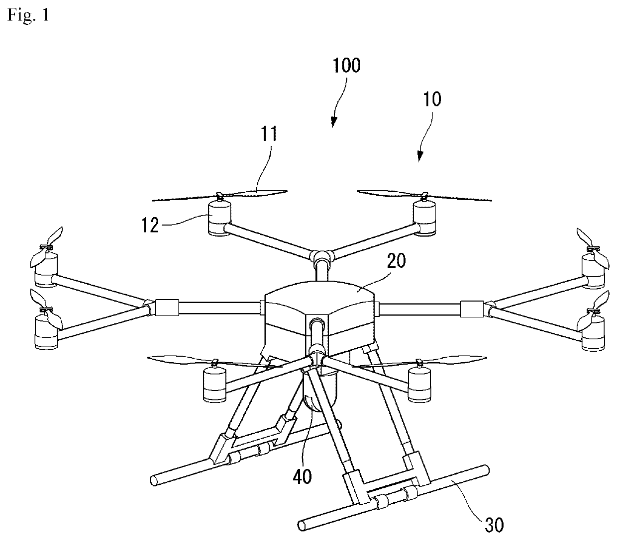
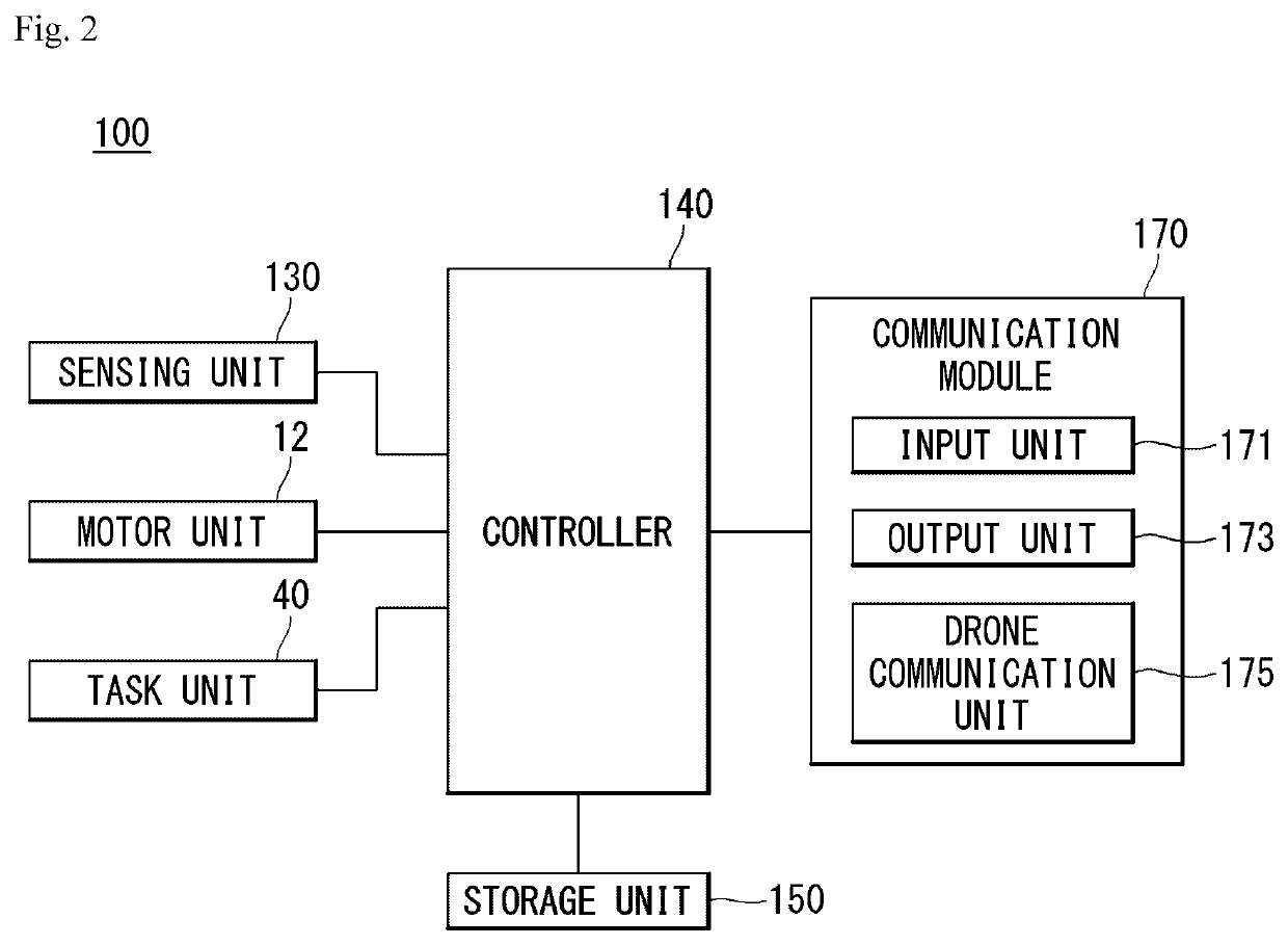
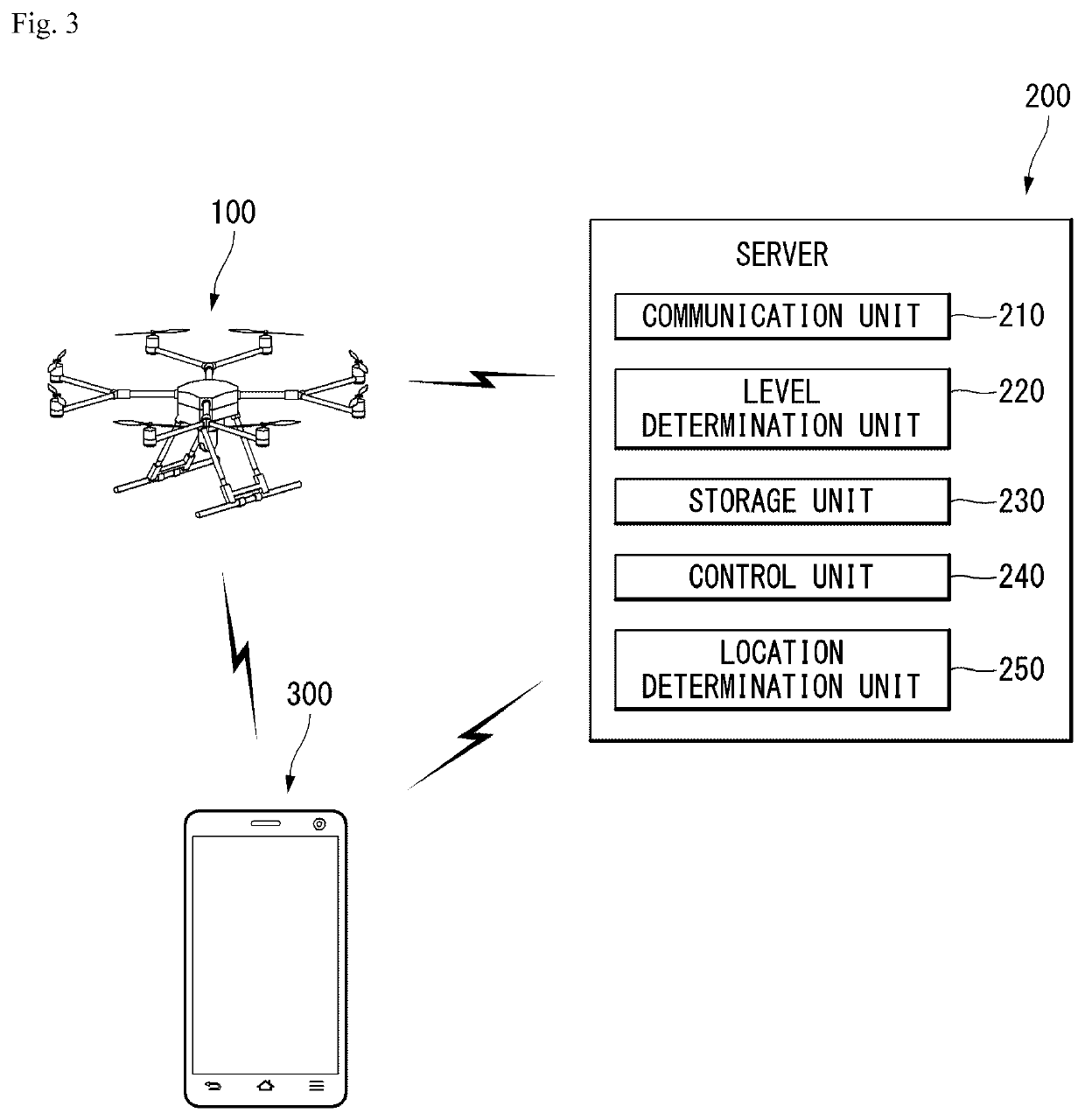
Provided is a method for controlling flight of a drone and an apparatus supporting the same. More specifically, the drone according to the present invention determines whether or not a specific condition is satisfied to deploy a parachute during the flight, and in a case where the specific condition is satisfied, the drone may stop an operation of one or more propellers to deploy the parachute. Next, the drone deploys the parachute, the parachute is deployed toward an area beside the drone, and the flight of the drone may be controlled by adjusting a rotation speed of each of the one or more propellers.

Description

CROSS-REFERENCE TO RELATED APPLICATIONS[0001]This application claims the benefit of Korea Patent Application No. 10-2019-0104751 filed on Aug. 26, 2019, which is incorporated herein by reference for all purposes as if fully set forth herein.BACKGROUND OF THE INVENTIONField of the Invention[0002]The present invention relates to an unmanned aerial system, and more particularly, to a method for increasing a flight duration by controlling flight of an unmanned aerial robot and an apparatus supporting the same.Related Art[0003]An unmanned flight object collectively refers to an unmanned aerial vehicle (or uninhabited aerial vehicle) (UAV) that is provided in a shape of an aircraft or a helicopter, and flies and steers by induction of radio waves without a pilot. In recent years, the unmanned flight object is widely used in various private commercial fields such as capturing of images, an unmanned delivery service, and a disaster observation, in addition to the military purposes such as r...

Claims


Application Information

Patent Timeline
IPC IPC(8): G05D1/00B64C39/02B64C25/32B64D17/34B64D17/62B64D27/24G05D1/10
CPCB64C2201/128G05D1/0072B64D27/24B64C2201/141B64C25/32H04W84/042B64C2201/126B64D17/34B64C2201/165B64C2201/185B64C2201/127B64C2201/146B64D17/62B64C39/024B64C2201/123G05D1/0022G05D1/101B64C2201/042B64C2201/108G05D1/0858G05D1/105B64U70/83B64U2201/20B64U10/16B64U50/23B64U60/50B64U30/29B64D17/80B64D45/00Y02T50/60B64U2201/10B64U2201/104
Inventor JEONG, YUSEUNGLEE, SANGHAKSEO, JEONGKYO
Owner LG ELECTRONICS INC
Learn More