Cutting insert and tool for machining a workpiece
- Summary
- Abstract
- Description
- Claims
- Application Information
AI Technical Summary
Benefits of technology
Problems solved by technology
Method used
Image

Examples
Embodiment Construction
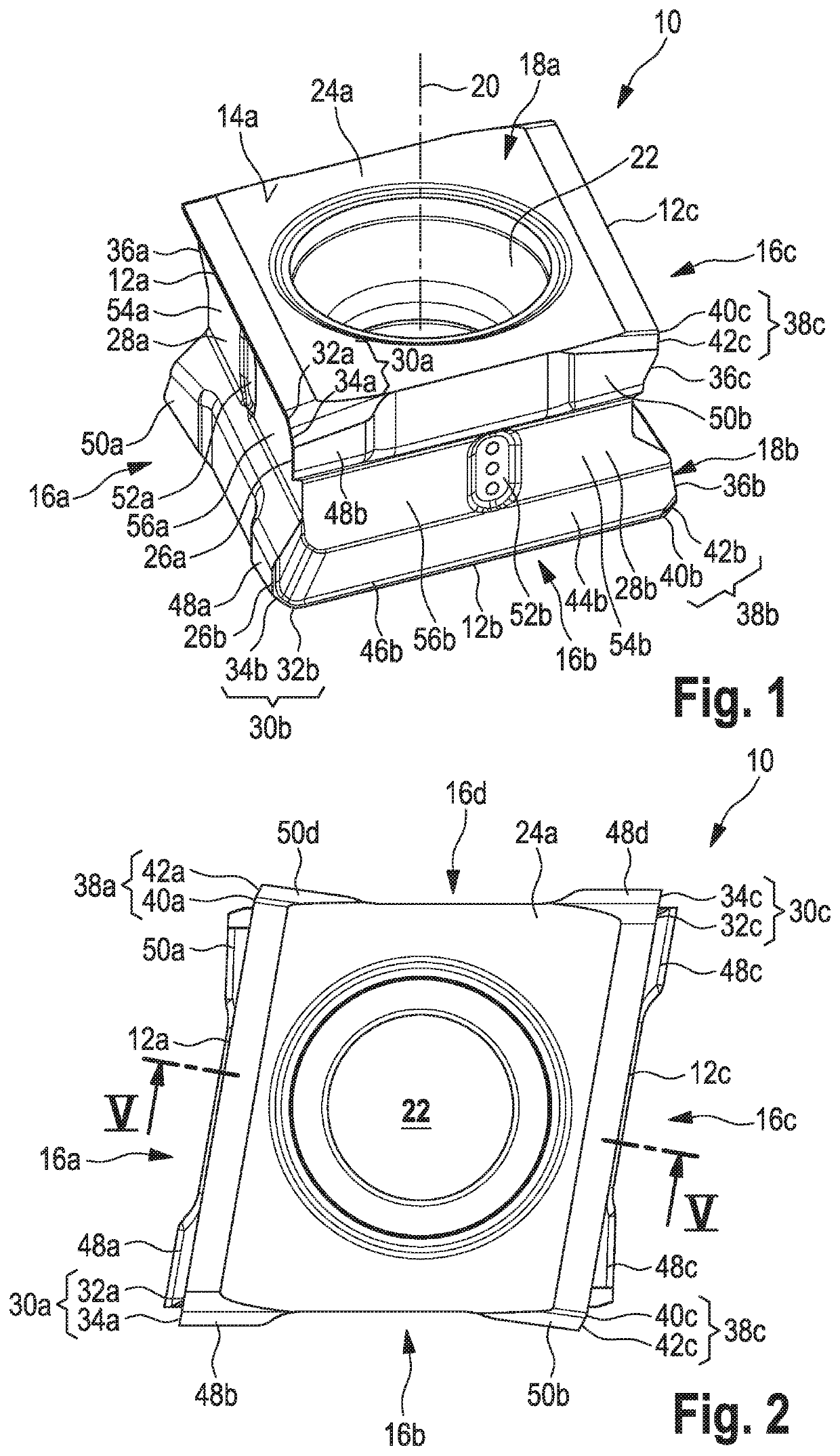
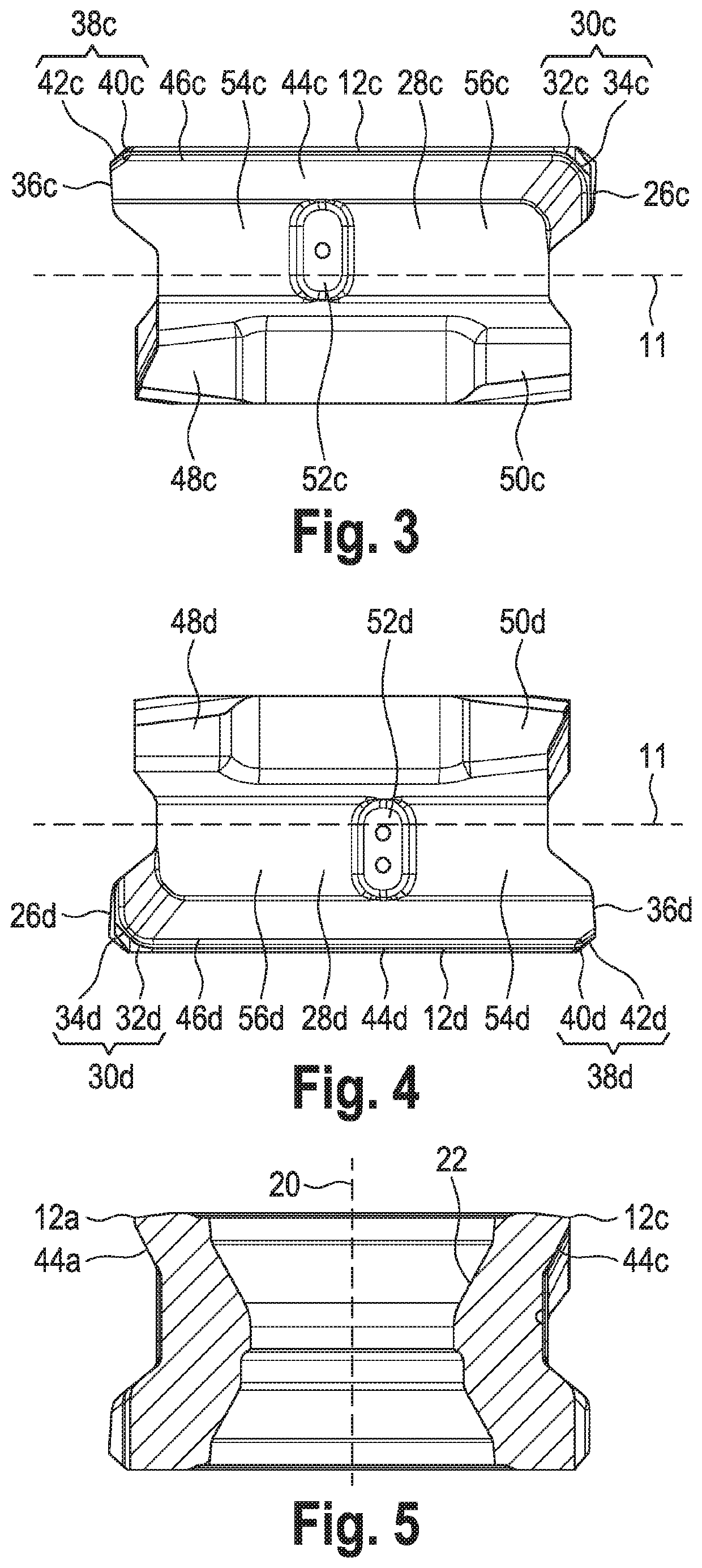
[0066]FIGS. 1-5 show various views of an embodiment of the cutting insert according to this disclosure as an example, the cutting insert being characterized in each case as a whole by the reference numeral 10. It can be seen from the perspective view shown in FIG. 1 that this is a four-bladed indexable insert 10, with four identical, rectilinear main cutting edges 12a-12d (main cutting edge 12d is hidden in FIG. 1, see for example FIG. 4 in this respect).
[0067]The outer form of the cutting insert 10 is delimited by a total of six sides: two oppositely arranged base sides 14a, 14b which form the top and bottom sides of the cutting insert 10, as well as four main sides 16a-16d which are also designated as main insert sides 16a-16d.
[0068]The two base sides 14a, 14b are designed identically to one another in the present exemplary embodiment. The four main sides 16a-16d are designed substantially identically to one another according to the present exemplary embodiment. They differ only ...
PUM
 Abstract
Description
Claims
Application Information