Non-contact power transmission system

Active Publication Date: 2020-02-06
HONDA MOTOR CO LTD
View PDF0 Cites 2 Cited by
  • Summary
  • Abstract
  • Description
  • Claims
  • Application Information

AI Technical Summary

Benefits of technology

The present invention provides a non-contact power transmission system for vehicles that optimizes charging efficiency. The system uses a collision detection feature to ensure safe and reliable positioning of the vehicle's power reception unit with respect to the power transmission unit. Additionally, the system takes into account the difference in height between the power transmitting and receiving coils at various charging stations, allowing for accurate positioning at any location. Overall, the system ensures efficient charging of the vehicle's energy storage device.

Problems solved by technology

Although such positioning is performed prior to main charging, when such positioning is performed, a weak power for positioning is transmitted from the charging station, from the viewpoints of power savings, suppression of electromagnetic interference (EMI), and the like.

Method used


Image

  • Non-contact power transmission system
  • Non-contact power transmission system
  • Non-contact power transmission system

Examples


first example

[0089][Procedure for Detecting Relative Position of Power Receiving Coil 12 with Respect to Power Transmitting Coil 11]

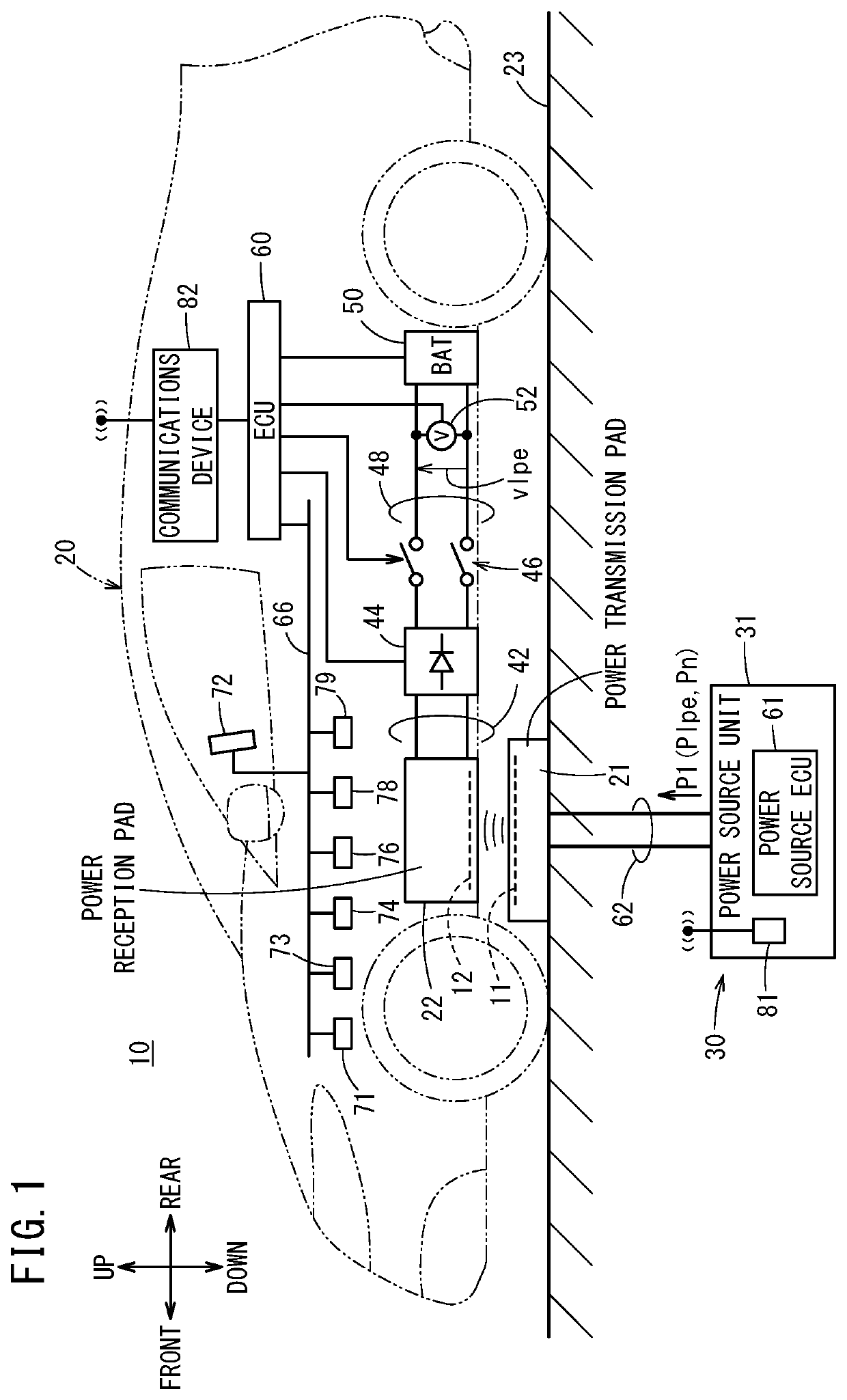
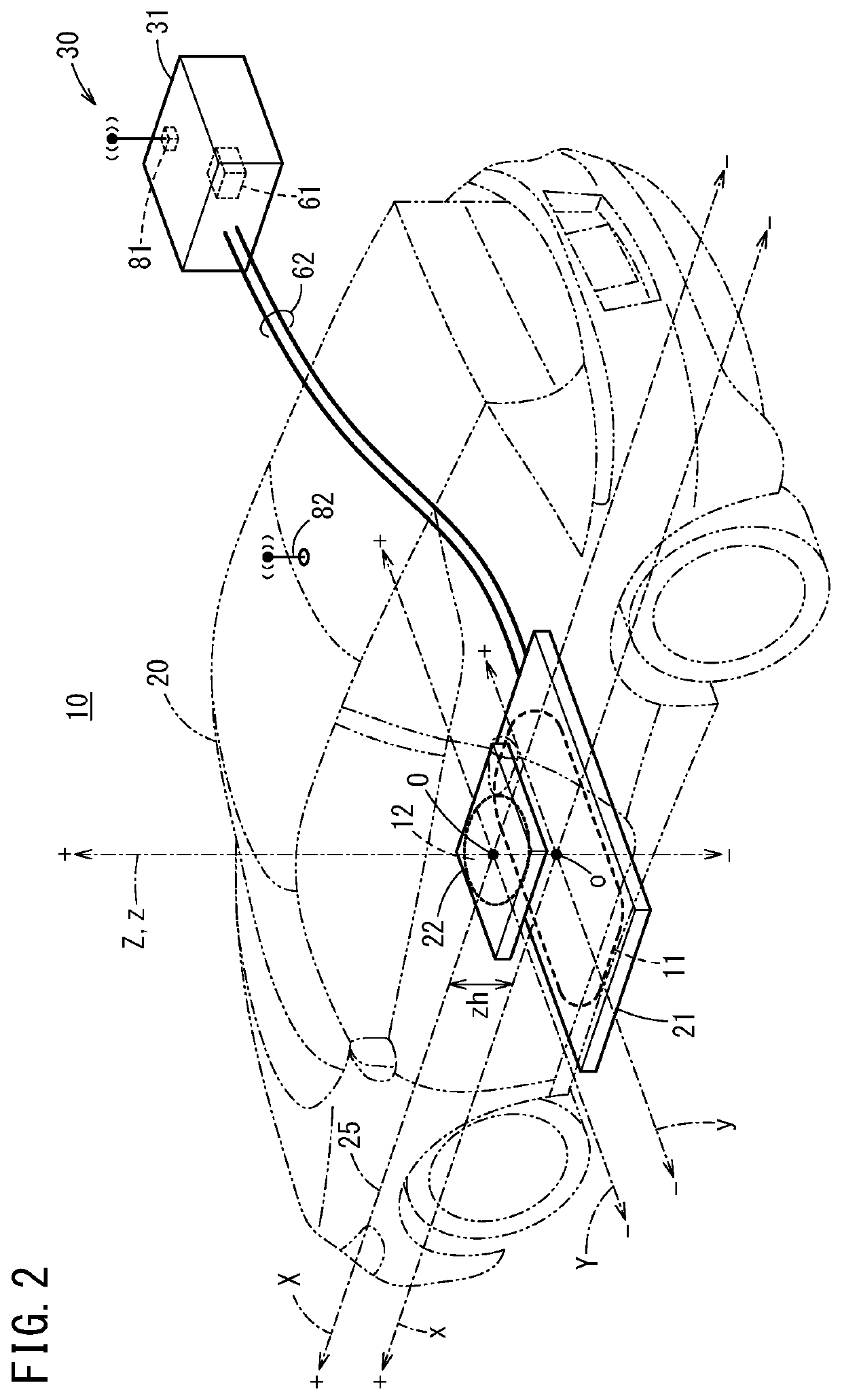
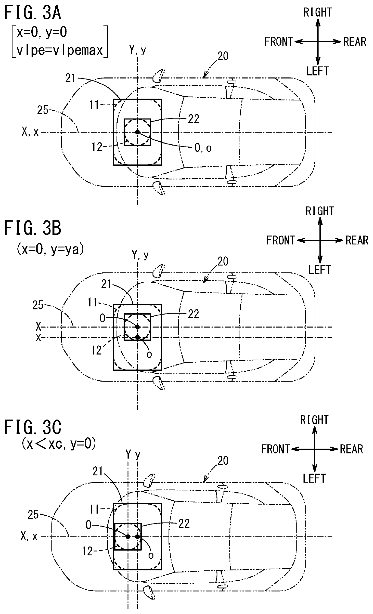
[0090]FIG. 5 is a schematic plan view in which, concerning the position of the vehicle 20 shown on the upper side in the drawing, a position is shown at which the vehicle 20, which is currently traveling rearward from an upper (positive side) position of the x-axis in the same drawing toward the center o of the power transmission pad 21 (power transmitting coil 11), and while the weak power Plpe is being transmitted from the power transmitting coil 11 after pairing, detects with the voltage value detection unit 102 of the vehicle 20 the weak voltage for the first time through the voltage sensor 52, and the weak voltage value vlpe (vlpe=0+) is detected.

[0091]When the weak voltage value vlpe is detected for the first time, the ECU 60 refers to the weak voltage value characteristic 202, and sets the position to an initial position xint {xint=(x, y)=(xint, 0)} of a know...

second example

[Identification and Determination of Weak Voltage Detection Range Exterior Region Dout and Weak Voltage Detection Range Interior Region Din]

[0158]As described above, according to the present embodiment, basically, the movement amount xvp of the power receiving coil 12 on the x-axis from the initial position xint where the weak voltage value vlpe is initially received, or stated otherwise, the x-axis position (distance) x from the origin point o of the power transmitting coil 11 is calculated.

[0159]Therefore, in the detection range exterior region Dout, parameters such as the weak voltage integrated value vilpe and the x-axis movement amount xvp are reset, and if the vehicle 20 enters the detection range interior region Din (when entering from outside of the detection range to the interior of the detection range), by resetting the parameters such as the weak voltage integrated value vilpe and the x-axis movement amount xvp, initialization is carried out to set the initial position xi...

third example

[0168][Procedure for Calculating x-Axis Movement Amount Xvp]

[0169]In FIG. 9, there is shown the weak voltage value characteristic 2020s (at which the z-axis height zh is zh1) and a weak voltage value characteristic 2020s′ (at which the z-axis height zh is zh2, zh2>zh1), which are drawn on both positive and negative sides of the origin point o of the x-axis.

[0170]The weak voltage value characteristic 2020s′ is the characteristic occurring at a time when the z-axis height is zh=zh2, which is higher than the z-axis height of zh=zh1, and the weak voltage value vlpe is a low value within the entire detection range interior region Din.

[0171]For example, when the vehicle 20 enters the detection range interior region Din(+) from the detection range exterior region Dout(+), the weak voltage position differential value vdplpe as indicated by the expression (3) transitions from a zero value (vdplpe=0) to a non-zero value (vdplpe #0).

[0172]As shown in FIG. 10A, the position where the weak volta...


PUM


Abstract

Provided s a non-contact power transmission system with which it is possible to individually detect the position of a receiving unit with respect to a transmission unit, even if there are positions at which the same microvoltage values are indicated, even if the distance differs, due to the shape of the transmission coil of the transmission unit and the receiving coil of the receiving unit. At a position at which the position differential value of the detected microvoltage exceeds a zero value, said positions set to the initial position (+xint) of the movement displacement of the vehicle, and the movement displacement on the basis of vehicle velocity is calculated to a position (+xc) at which the microvoltage value characteristics can be used from said initial position to (+xc to 0).

Description

TECHNICAL FIELD[0001]The present invention relates to a non-contact power transmission system that carries out positioning of a vehicle including an energy storage device with respect to a charging station.BACKGROUND ART[0002]In this type of non-contact power transmission system, main charging of the energy storage device of the vehicle is carried out with a steady power (normal power) transmitted from the charging station, after the vehicle body has been positioned with respect to the charging station.[0003]Although such positioning is performed prior to main charging, when such positioning is performed, a weak power for positioning is transmitted from the charging station, from the viewpoints of power savings, suppression of electromagnetic interference (EMI), and the like.[0004]The vehicle having received the weak power travels for the purpose of performing positioning on the basis of the weak power, so as to position the vehicle at the charging station.[0005]At the position of t...

Claims


Application Information

Patent Timeline
IPC IPC(8): B60L53/38B60L50/60H02J50/10B60L53/126B60L53/36H02J50/90
CPCB60L53/36H02J50/90H02J50/10B60L50/60H01F38/14B60L53/38B60L53/126B60L50/50H02J2310/48Y02T10/70Y02T10/7072Y02T90/14Y02T90/12H02J7/0042
Inventor SAITA, AKIRA
Owner HONDA MOTOR CO LTD
Why Eureka
Try Eureka