
Support collar for cables, pipes or the like

a technology for supporting collars and cables, applied in the direction of pipe supports, electrical appliances, pipes/joints/fittings, etc., can solve the problems of collars, limit the possibility of freeing the shape and dimensions of the arms of the clips from the dimensions of the side portions, and the inability to adapt, without the use of sleeves, to cables or pipes having an extremely reduced diameter. , to achieve the effect of reducing production and marketing costs

Active Publication Date: 2020-02-06
FI MOTEC SPA
View PDF7 Cites 20 Cited by
  • Summary
  • Abstract
  • Description
  • Claims
  • Application Information

AI Technical Summary

Benefits of technology

The present invention aims to provide stackable support collars that are easy to position and securely lock cables and pipes. Additionally, the invention reduces production and marketing costs. Furthermore, the support collars can eliminate the problem of passive intermodulation.

Problems solved by technology

This allows a saving of the material used for the production of the support collars; however, it limits the possibility of freeing the shape and dimensions of the arms of the clip from the dimensions of the side portions.
It is evident, however, also from the figures, that the collar described in document EP 2464907 cannot adapt, without the use of sleeves, to cables or pipes having an extremely reduced diameter.
Undesired signals due to passive intermodulation are generated due to some form of mechanical non-linearity.
One of the major causes is the inconsistency of the contacts between metal and metal in the areas affected with high current intensities, such as those inside the transmission lines or within the radiofrequency (RF) components.
This may be due to the imperfect preparation of the RF terminations or non-optimal assembly procedures, loosening of screws or rivets inside the RF components, contaminated or oxidized surfaces of the connectors or RF connectors that are not properly tightened.

Method used


Image

  • Support collar for cables, pipes or the like
  • Support collar for cables, pipes or the like
  • Support collar for cables, pipes or the like

Examples


Embodiment Construction

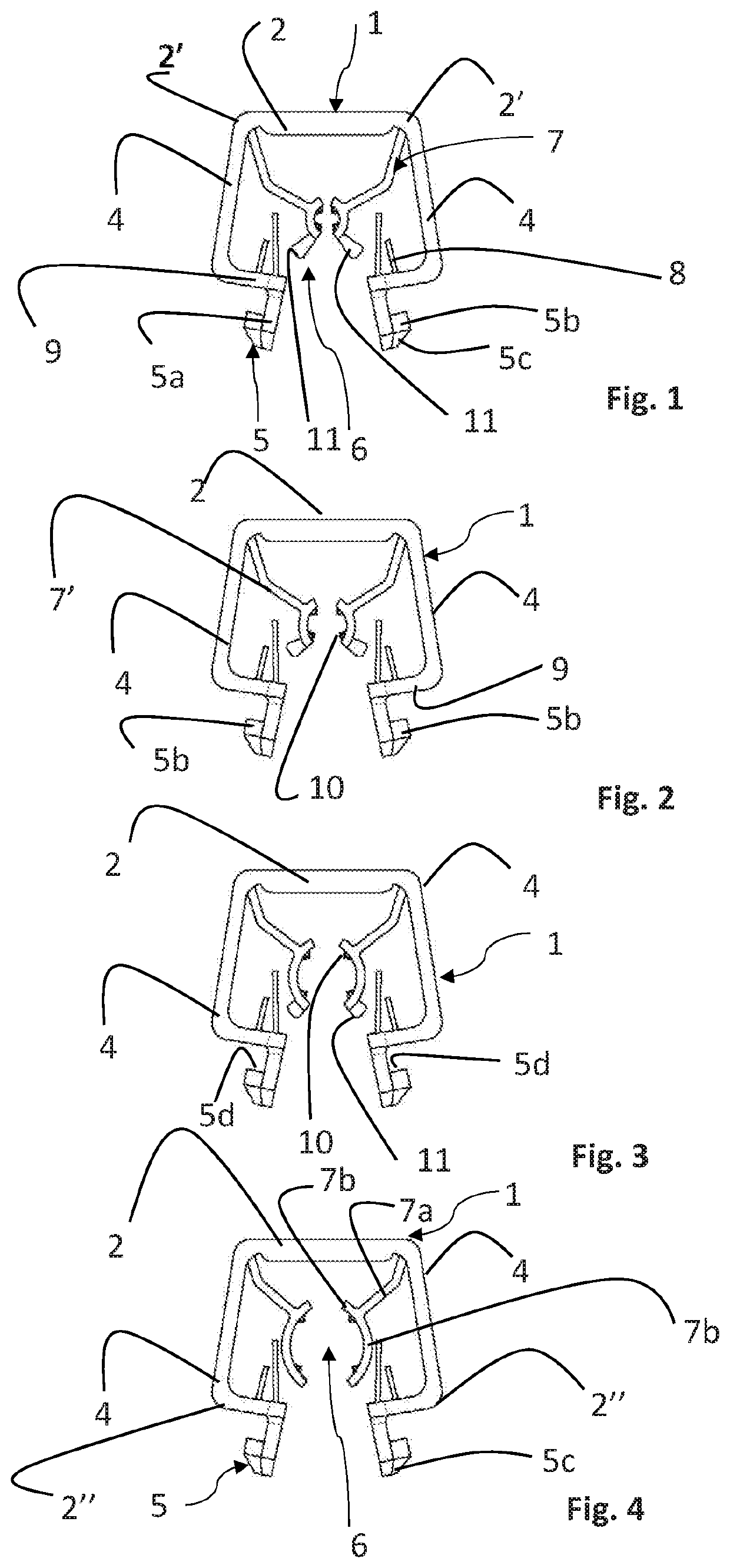
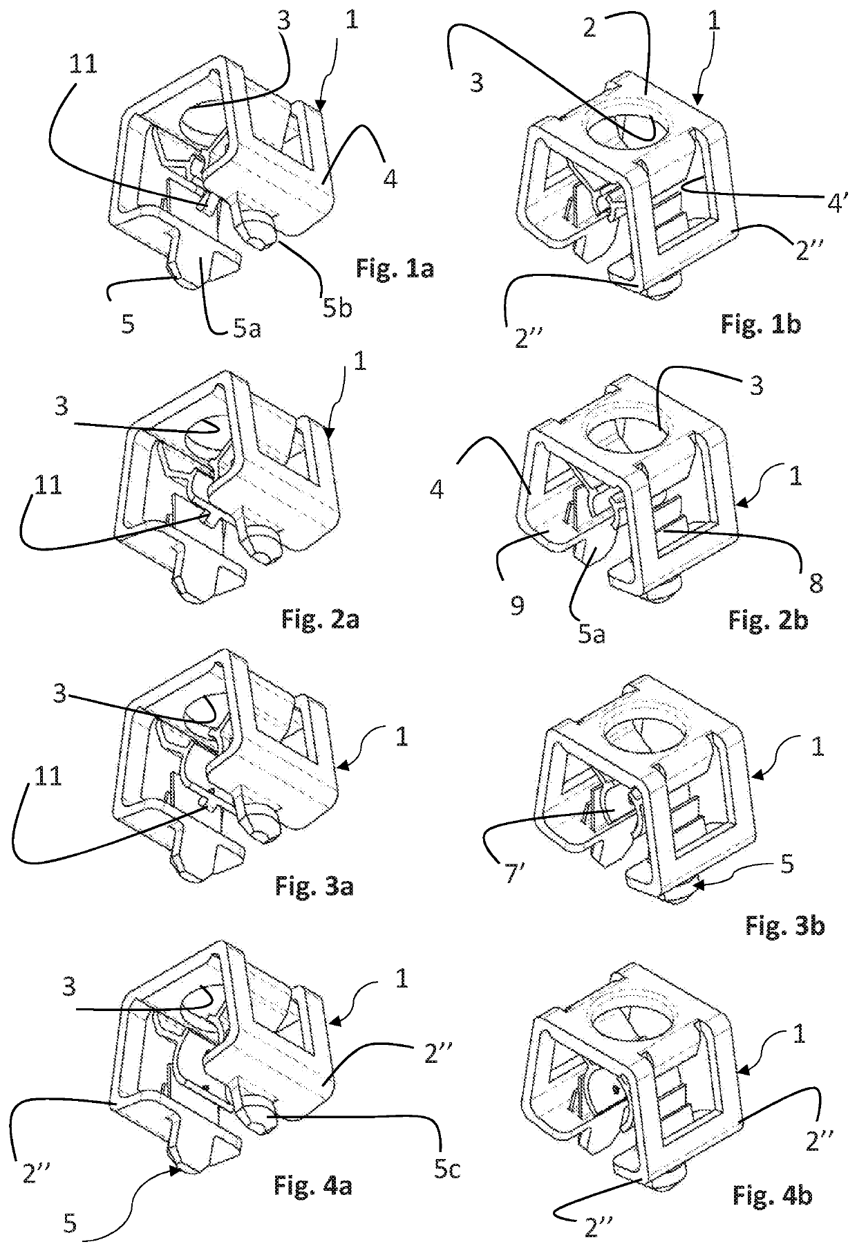
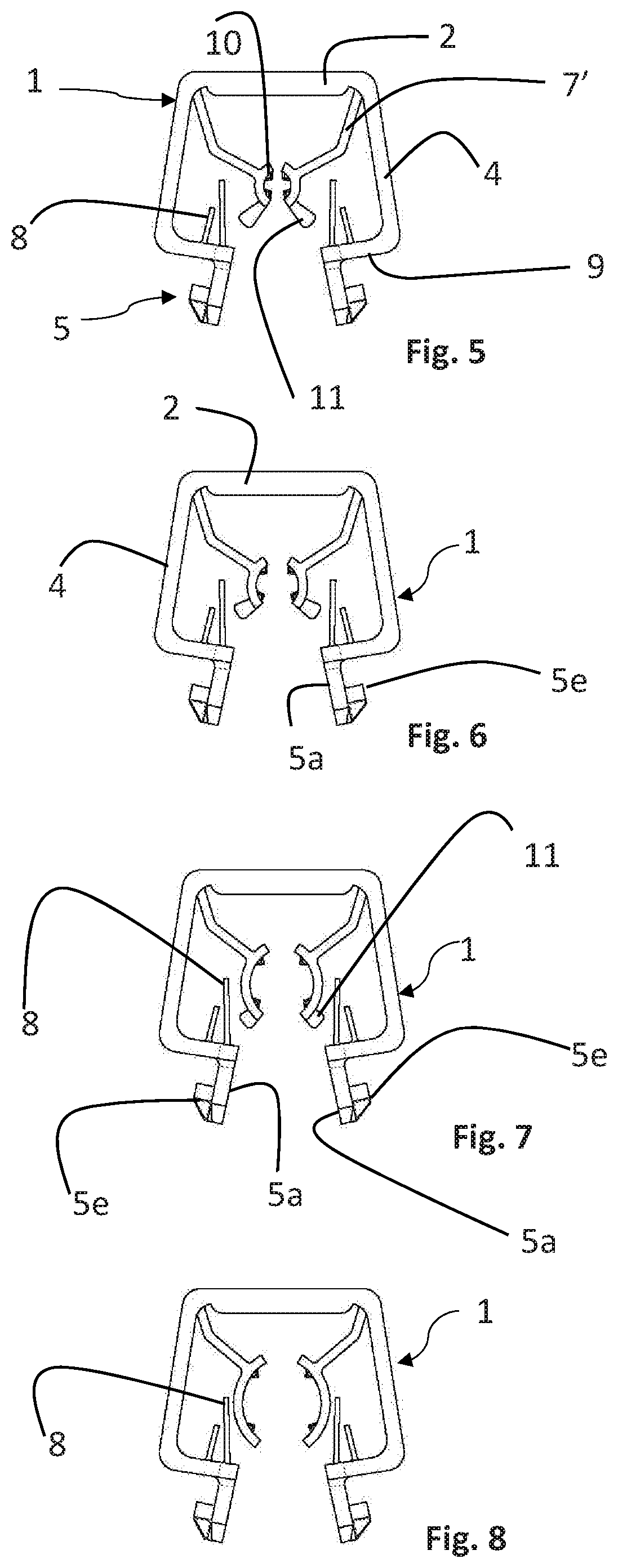
[0042]With reference to the figures, a support collar for cables, pipes or the like is indicated as a whole with 1.

[0043]The support collar 1 is made of a plastic material.

[0044]In particular it is made of a flexible, elastic and resistant plastic material.

[0045]According to the present invention the support collar 1 for cables, pipes or the like comprises:

[0046]a head portion 2, having at least one pass-through opening 3;

[0047]two side portions 4 extending transversely and substantially perpendicularly from said head portion 2 and ending with two respective abutment portions 9 positioned parallel to said head portion 2;

[0048]each of said abutment portions 9 being provided with at least one respective coupling element 5 suitable for engaging said collar 1 on a support plate 15 or a head portion 2 of a further support collar 1, said side portions 4, said abutment portions 9 and said head portion 2 of said support collar 1 delimiting an area 6 for the partial housing of said cable or ...


PUM


Abstract

A support collar for cables, pipes or the like includes a head portion having a pass-through opening; two side portions extending from the head portion and ending with abutment portions disposed substantially parallel to the head portion and with a coupling element adapted to engage the collar onto a support plate or the head portion of another support collar; and retaining members within the housing area for retaining firmly the cable or pipe. The retaining members include a clip having retaining arms that extend inside the housing area and can be elastically splayed to engage the cable or pipe due to an elastic pressure exerted transversely thereon. Each of the retaining arms cooperates with a flap that extends into the housing area opposite of the retaining arms, so that the flap is abutted against the retaining arm when the cable or pipe is engaged in the clip.

Description

FIELD OF THE INVENTION[0001]The present invention relates to a support collar for cables, tubes or the like.BACKGROUND OF THE INVENTION[0002]As it is known, the supporting of cables or pipes in the telecommunications and building sector is achieved by using one or more support collars that can be fixed on perforated plates.[0003]Support collars in fact comprise relatively elastic structures obtained by means of respective open profiles, which can be splayed to be rapidly fitted onto the cables or tubes to be supported.[0004]In document EP 2464907, a support collar is described comprising a laminar structure provided with a flat head portion with a central opening, two side portions extending transversely from said head portion and each having a coupling element suitable for engaging said collar on a support plate or a flat head portion of a further support collar, a retaining clip for a long-shaped article positioned in the area determined by said head portion and said two side port...

Claims


Application Information

Patent Timeline
IPC IPC(8): F16L3/10F16L3/13
CPCF16L3/13F16L3/1075H02G3/32F16L3/222
Inventor VARALE, ALBERTO
Owner FI MOTEC SPA
Learn More