Vehicle thermal system architecture

Active Publication Date: 2020-02-13
GM GLOBAL TECH OPERATIONS LLC
View PDF0 Cites 21 Cited by
  • Summary
  • Abstract
  • Description
  • Claims
  • Application Information

AI Technical Summary

Problems solved by technology

The scavenging functions are often performed on dedicated heating, cooling, or electrical circuits, leading to a relatively complex series of circuits, many of which function almost entirely independent of one another.
However, even though ICEs have, and will likely continue to become, more and more efficient, substantial quantities of thermal energy are generated by the ICEs, a significant amount of which is usually rejected to the vehicle's surroundings.
That is, in an ICE-powered vehicle, a surplus of thermal energy is ge

Method used


Image

  • Vehicle thermal system architecture
  • Vehicle thermal system architecture
  • Vehicle thermal system architecture

Examples


Embodiment Construction

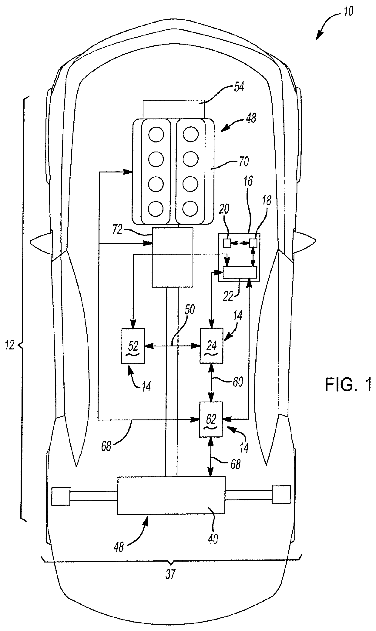
[0024]Example illustrations herein are directed to a vehicle and thermal energy management system that allow circulation and accumulation of thermal energy to meet various needs of the vehicle, such as heating or cooling of a passenger compartment of the vehicle, or of vehicle components themselves. Example illustrations may circulate thermal energy via a relatively reduced number of thermal fluid loops, thereby simplifying operation of the thermal energy management system, and facilitating storage of otherwise less useful or “low-quality” thermal energy. The storage of this “low-quality” thermal energy in, for example, various heat sinks of the vehicle may allow thermal energy to be reused instead of rejected from the vehicle.

[0025]Referring to FIG. 1, a motor vehicle is shown and indicated generally by reference number 10. While the motor vehicle 10 is depicted as a car, it should be understood that the motor vehicle 10 may be a car, a truck, an SUV, a van, a semi, a tractor, a bu...


PUM


Abstract

A thermal energy management system for a vehicle is provided that is configured to supply thermal energy to a passenger compartment of the vehicle. The thermal energy management system may include three thermal fluid loops. The first thermal fluid loop may include a coolant pump circulating a coolant through at least a vehicle battery, a transmission oil cooler of the vehicle, and a chiller such that the coolant is configured to selectively transfer thermal energy from the vehicle battery, the transmission oil cooler, and the chiller. The second thermal fluid loop may circulate oil through the transmission oil cooler. The third thermal fluid loop may circulate a refrigerant through at least the chiller and at least one condenser such that the third thermal fluid loop is configured to transfer thermal energy to the passenger compartment.

Description

INTRODUCTION[0001]The statements in this section merely provide background information related to the present disclosure, and may not constitute prior art.[0002]The present disclosure relates to motor vehicle thermal management systems, and more specifically to systems and methods for controlling the operation of thermal energy sources and sinks within a motor vehicle. Emissions standards, environmental concerns, and operator perceptions of responsiveness, smoothness and noise, vibration, and harshness (NVH), as well as operator comfort dictate many of the ways in which thermal energy within a motor vehicle is controlled. Traditionally, efficiencies have been sought within the confines of the internal combustion engines (ICE) functioning as prime movers for motor vehicles. Such advances have generally taken the form of improving combustion efficiency (maximizing combustion energy conversion into motive force), scavenging combustion thermal energy to run heating / ventilation / air condi...

Claims


Application Information

Patent Timeline
IPC IPC(8): B60H1/00B60H1/32B60H1/14
CPCB60H1/00899B60H2001/00928B60H1/143B60H1/3227B60H1/00385B60H1/00007B60H2001/006B60H1/00278B60H1/32F16H57/0413B60L58/26B60L58/27B60H2001/003B60H1/00914B60H2001/00949B60H2001/00307Y02T10/70
Inventor GONZE, EUGENE V.ZIEHR, LAWRENCE P.KETKAR, SATISH P.CARLSON, MICHAEL H.
Owner GM GLOBAL TECH OPERATIONS LLC
Why Eureka
Try Eureka