Water jet propulsion boat
a technology for propulsion boats and water jets, applied in marine propulsion, special-purpose vessels, vessel construction, etc., can solve problems such as difficulty in maintaining related-art boats in boat stop states in cases
- Summary
- Abstract
- Description
- Claims
- Application Information
AI Technical Summary
Benefits of technology
Problems solved by technology
Method used
Image
Examples
first embodiment
(Configuration)
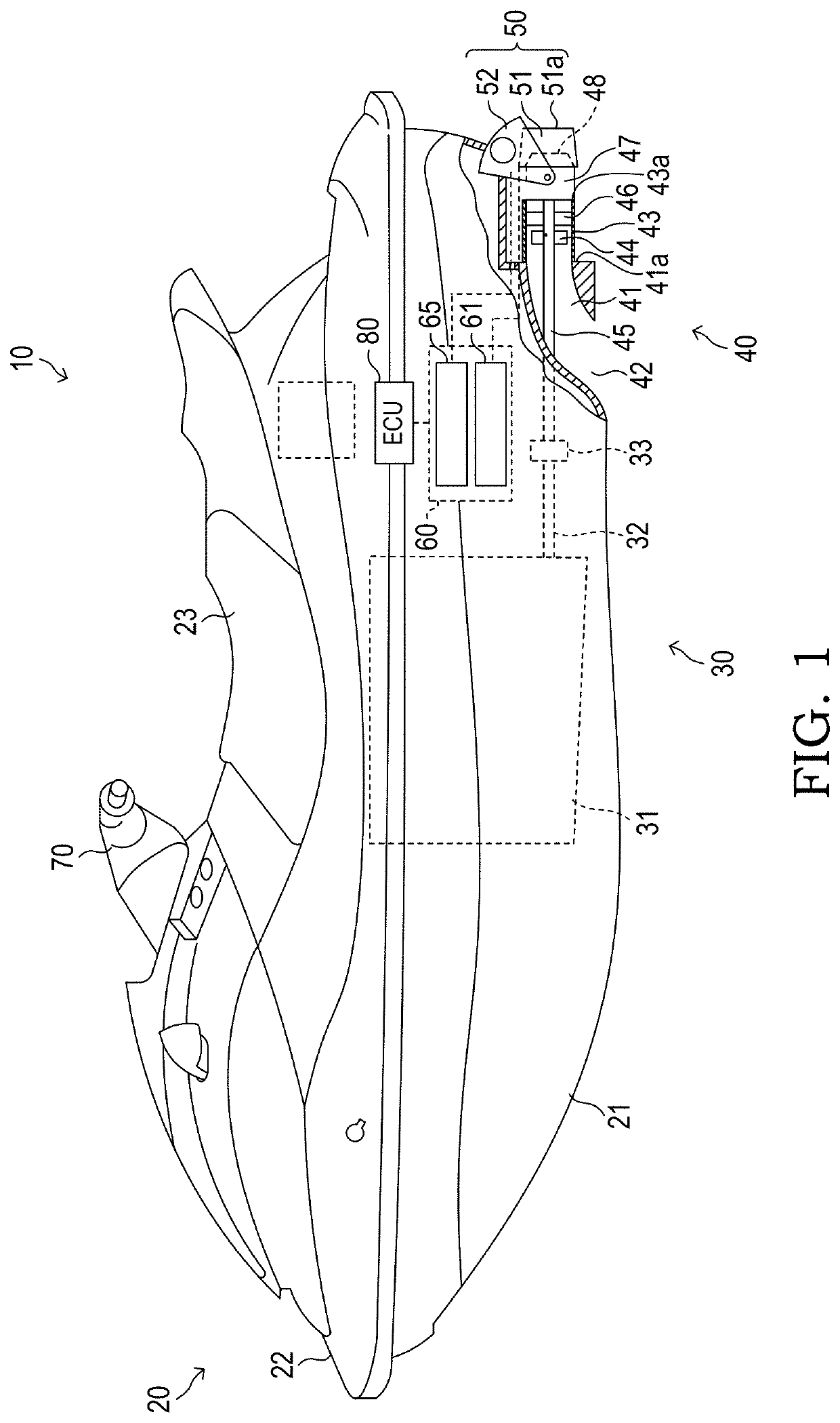
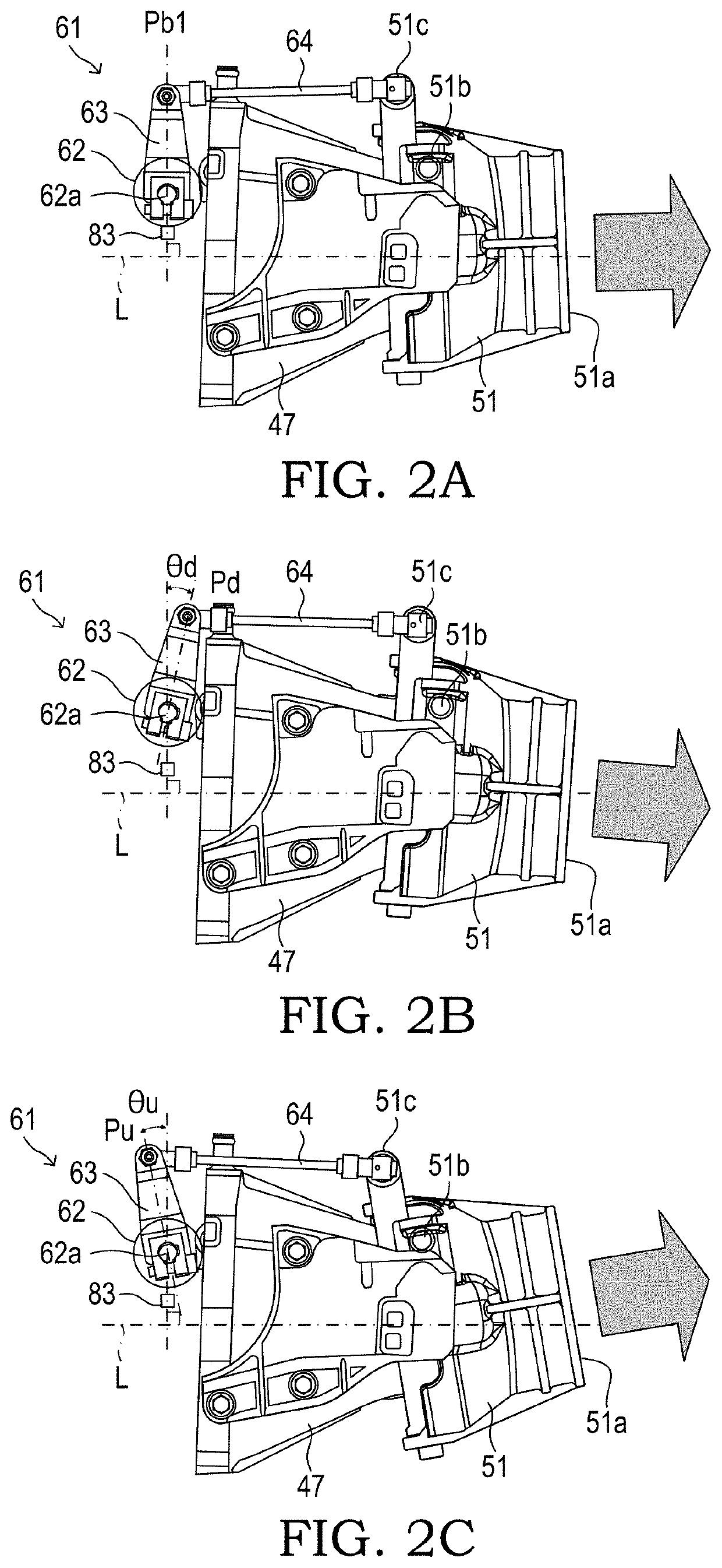
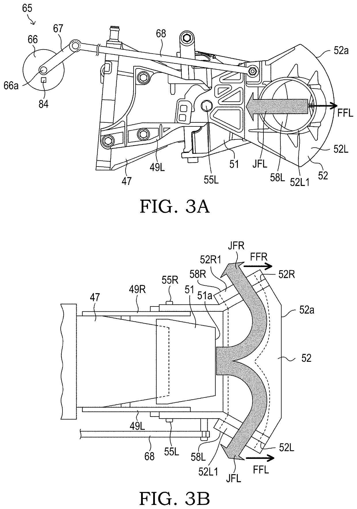
[0035]As illustrated in FIG. 1, a water jet propulsion boat (hereinafter also referred to as “first jet propulsion boat”) 10 according to a first embodiment includes, for example, a boat body 20, a drive device 30, a jet flow generation device 40, a jet flow adjustment member 50, an actuator 60, an operation part 70, and a control device (ECU) 80.
[0036]The boat body 20 includes a hull 21, a deck 22, and a seat 23. The hull 21 forms a boat bottom. The deck 22 is arranged above the hull 21. The seat 23 is arranged at a center of the deck 22 in a right-and-left direction, and is configured to allow an operator (occupant) (not shown) to be seated thereon.
[0037]The drive device 30 includes an engine 31, a crankshaft 32, and a coupling 33. The drive device 30 is arranged in a space partitioned between the hull 21 and the deck 22. The engine 31 is a multi-cylinder internal combustion engine of a spark ignition type. The engine 31 is arranged below the seat 23. The crankshaft...
second embodiment
[0134]Description is now made of a water jet propulsion boat (hereinafter also referred to as “second jet propulsion boat 10A”) according to a second embodiment of the present invention. The control device (ECU) of the first jet propulsion boat 10 always moves the position of the reverse bucket 52 to the neutral position when the neutral operations have been carried out. The second jet propulsion boat 10A is different from the first jet propulsion boat 10 in that the movement position of the reverse bucket 52 at a time point immediately before any one of the forward-movement operations and the backward-movement operations is stored, and the reverse bucket 52 is moved to the stored movement position when the neutral operations are carried out next. Description is now mainly made of this difference.
[0135](Specific Operation of Second Jet Propulsion Boat)
[0136]With reference to FIG. 11, description is made of an actual operation of the second jet propulsion boat 10A.
[0137]A CPU of the ...
third embodiment
[0141]Description is now made of a water jet propulsion boat (hereinafter also referred to as “third jet propulsion boat 10B”) according to a third embodiment of the present invention. The control device (ECU) of the first jet propulsion boat 10 carries out the forward movement at very low speed and the backward movement at very low speed by moving the position of the reverse bucket 52 in accordance with the operation on the third operation element 75 when the neutral operations have been carried out. In contrast, the third jet propulsion boat 10B is different from the first jet propulsion boat 10 and the second jet propulsion boat 10A in that the forward movement at very low speed or the backward movement at very low speed is carried out by moving the position of the deflector 51 in accordance with the operation on the third operation element 75 when the neutral operations have been carried out. Description is now mainly made of this difference.
[0142]As illustrated in FIG. 12A, whe...
PUM
 Abstract
Description
Claims
Application Information
 - R&D Engineer
- R&D Manager
- IP Professional
- Industry Leading Data Capabilities
- Powerful AI technology
- Patent DNA Extraction
Browse by: Latest US Patents, China's latest patents, Technical Efficacy Thesaurus, Application Domain, Technology Topic, Popular Technical Reports.
© 2024 PatSnap. All rights reserved.Legal|Privacy policy|Modern Slavery Act Transparency Statement|Sitemap|About US| Contact US: help@patsnap.com


