Brake using magnetorheological transmission and brake-by-wire

a technology of magnetorheological transmission and actuator, which is applied in the direction of coupling-brake combination, clutch, mechanical apparatus, etc., can solve the problems of increasing the complexity of the system and control algorithm, the cost of the brake system remains high, and the system weight increases, so as to achieve the effect of high braking performance requirements, fast response and large controllable transmission torque rang

Active Publication Date: 2020-02-13
HEFEI UNIV OF TECH
View PDF0 Cites 9 Cited by
  • Summary
  • Abstract
  • Description
  • Claims
  • Application Information

AI Technical Summary

Benefits of technology

[0005]The present invention is to solve the current existing technical problems, providing a brake-by-wire actuator using motor-magnetorheological fluid clutch to meet higher braking performance requirements. The magnetorheological fluid clutch is a typical application using the magnetorheological fluid, which is a smart material with rheological properties. When under electromagnetic fields, its material properties (i.e., the shear stress

Problems solved by technology

However, the necessary pipelines/valves of the conventional hydraulic brake systems greatly increase the complexity of the system and control algorithm and also the system weight (which is unbeneficial to lightweight), and then the cost of the brake systems remains high.
At the same time, the long and sophisticated pipelines/valves of conventional hydraulic disc-type brake systems would lead to slow braking pressure transfer and then braking delay, which possibly results in the increase of braking distance and unguaranteed vehicle braking safety.
However,

Method used


Image

  • Brake using magnetorheological transmission and brake-by-wire
  • Brake using magnetorheological transmission and brake-by-wire
  • Brake using magnetorheological transmission and brake-by-wire

Examples


Embodiment Construction

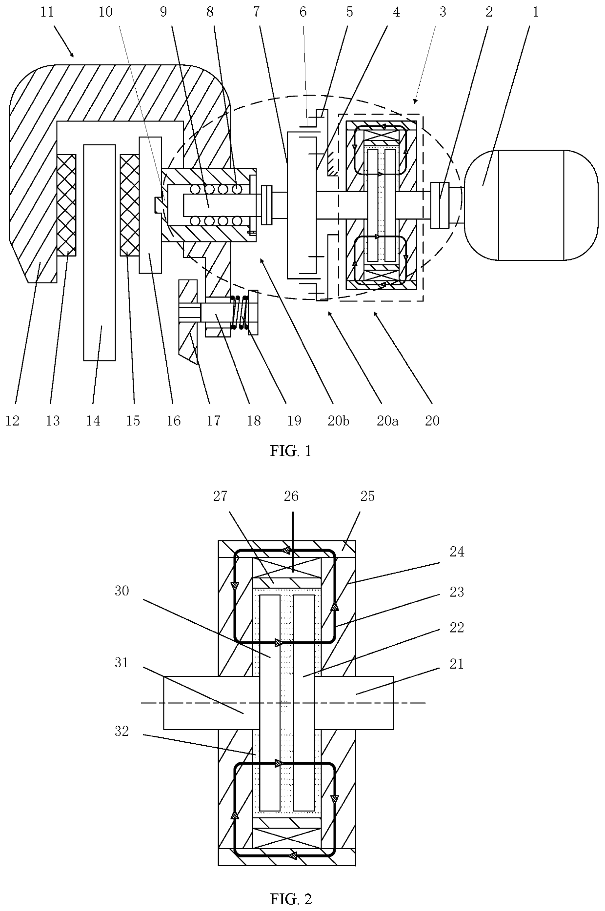
[0093]FIG. 1 shows a brake-by-wire actuator based on motor-magnetorheological fluid clutch, which in detail consists of a motor 1, a transmission mechanism 20 and a floating-caliper disc mechanism 11. The driving torque of the motor 1 is transmitted by the magnetorheological fluid clutch 3 in real time.

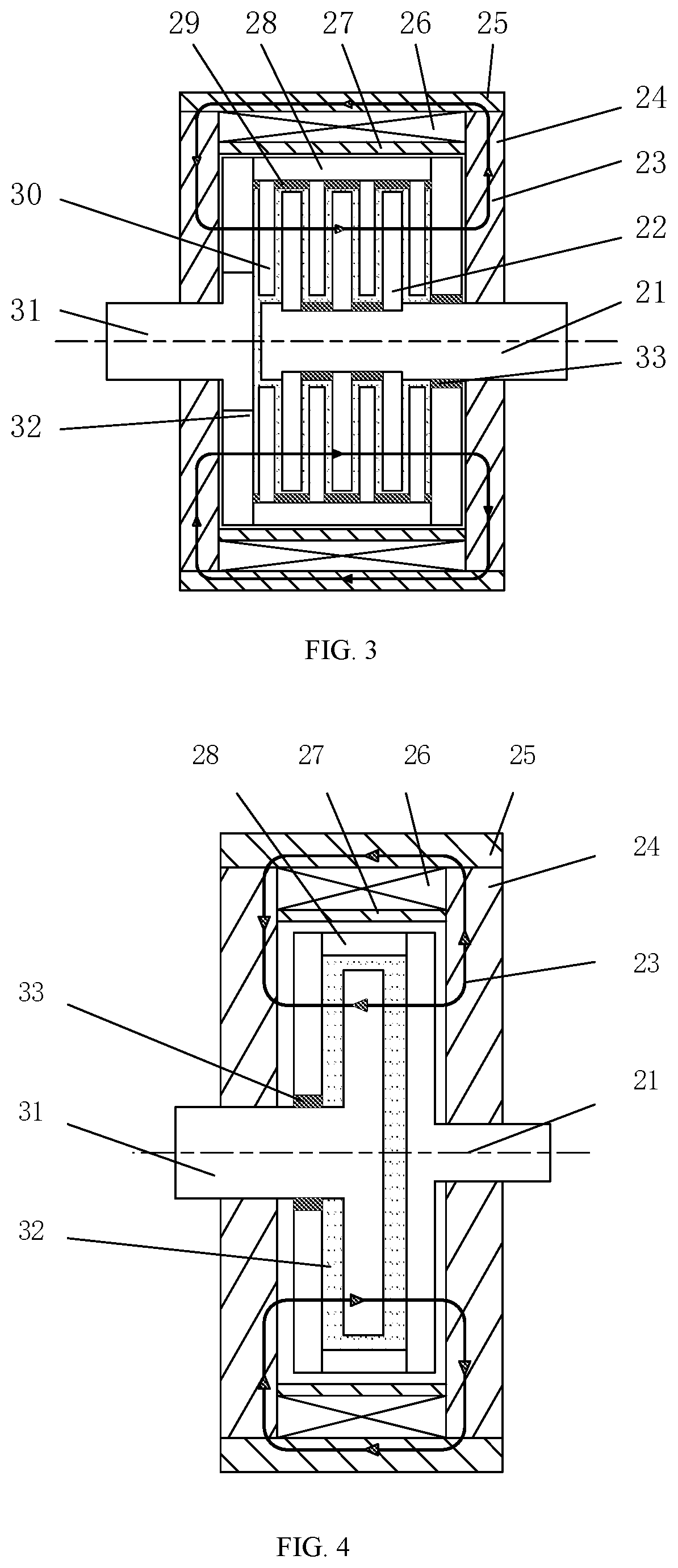
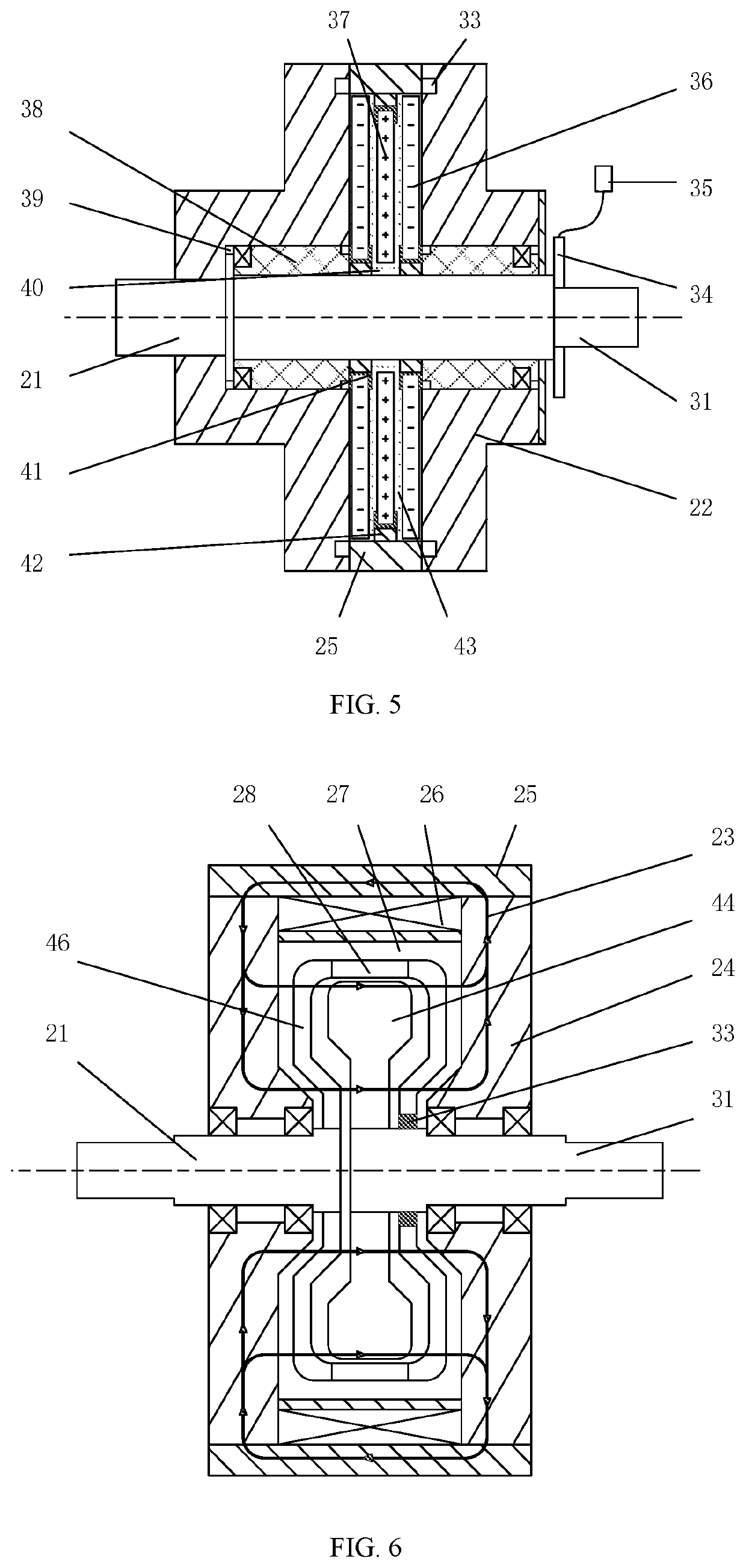
[0094]As shown in FIGS. 1 and 2, the transmission mechanism 20 includes a magnetorheological fluid clutch 3, a planetary gear set 20a and a ball screw set 20b. The magnetorheological fluid clutch 3 includes an input shaft 21 fixed to the input shear plate 22, a coil winding 26, an output shaft 31 fixed to the output shear plate 30 and magnetorheological fluid 32 fulfilled in the chamber. The planetary gear set 20a includes a sun gear 4, a ring gear 5, a planetary gear 6 and a carrier 7. The ball screw set 20b includes balls 8, a ball screw 9 and a sleeve 10. The electromagnetic field and the flux lines generated by the coil winding 26 are perpendicular to the magnetorheological fluid ...


PUM


Abstract

The present invention discloses a brake-by-wire actuator based on motor-magnetorheological fluid clutch. The system includes a motor, a transmission mechanism and a floating-caliper disc mechanism. The transmission mechanism includes a magnetorheological fluid clutch, a planetary gear set and a ball screw set. The ball screw set includes balls, a ball screw and a sleeve. The floating-caliper disc mechanism includes a brake pad back plate, left and right brake pads, a caliper body, a brake disc and a guide rail. The motor and the magnetorheological fluid clutch cascaded in series, the linear motion of the sleeve of the ball screw set is achieved by the magnetorheological fluid clutch and the transmission mechanism. The sleeve pushes forward the brake pad back plate of the floating-caliper disc mechanism to clamp the brake disc by left and right brake pads, which accomplishes braking. The present invention uses a brake-by-wire actuator based on motor-magnetorheological fluid clutch, which not only has the advantages of fast response and improved braking security, but also solves the problem of the motor stalling during long time braking.

Description

TECHNICAL FIELD[0001]The present invention relates to a floating-caliper disc brake, and more particularly to a brake-by-wire actuator using motor-magnetorheological fluid clutch.BACKGROUND OF THE INVENTION[0002]The background description provided herein is for the purpose of generally presenting the context of the disclosure. All description and statements in this background section, are neither expressly nor impliedly admitted as prior art against the present disclosure.[0003]Brake systems are an extremely important system to ensure the safety of the automobiles. Currently, the most reliable and widely used automotive brake system is the conventional hydraulic disc-type brake for the implementation of various braking purposes. The hydraulic disc-type brake includes a master cylinder, brake pipelines, a wheel cylinder, a caliper body, brake pads and a brake disc. When braking, the braking pressure generated from the master cylinder is delivered by brake pipelines to generate corres...

Claims


Application Information

Patent Timeline
IPC IPC(8): F16D67/06F16D55/226F16D65/18F16D37/00F16D35/00F16D37/02
CPCF16D65/183F16D55/226F16D2125/50F16D2121/20F16D2121/14F16D2121/24F16D37/02F16D37/008F16D35/00F16D67/06F16D2125/40F16D55/2245F16D65/14F16D67/02F16D63/002F16D2121/28
Inventor BAI, XIANXULIU, YANGLI, YANG
Owner HEFEI UNIV OF TECH
Why Eureka
Try Eureka