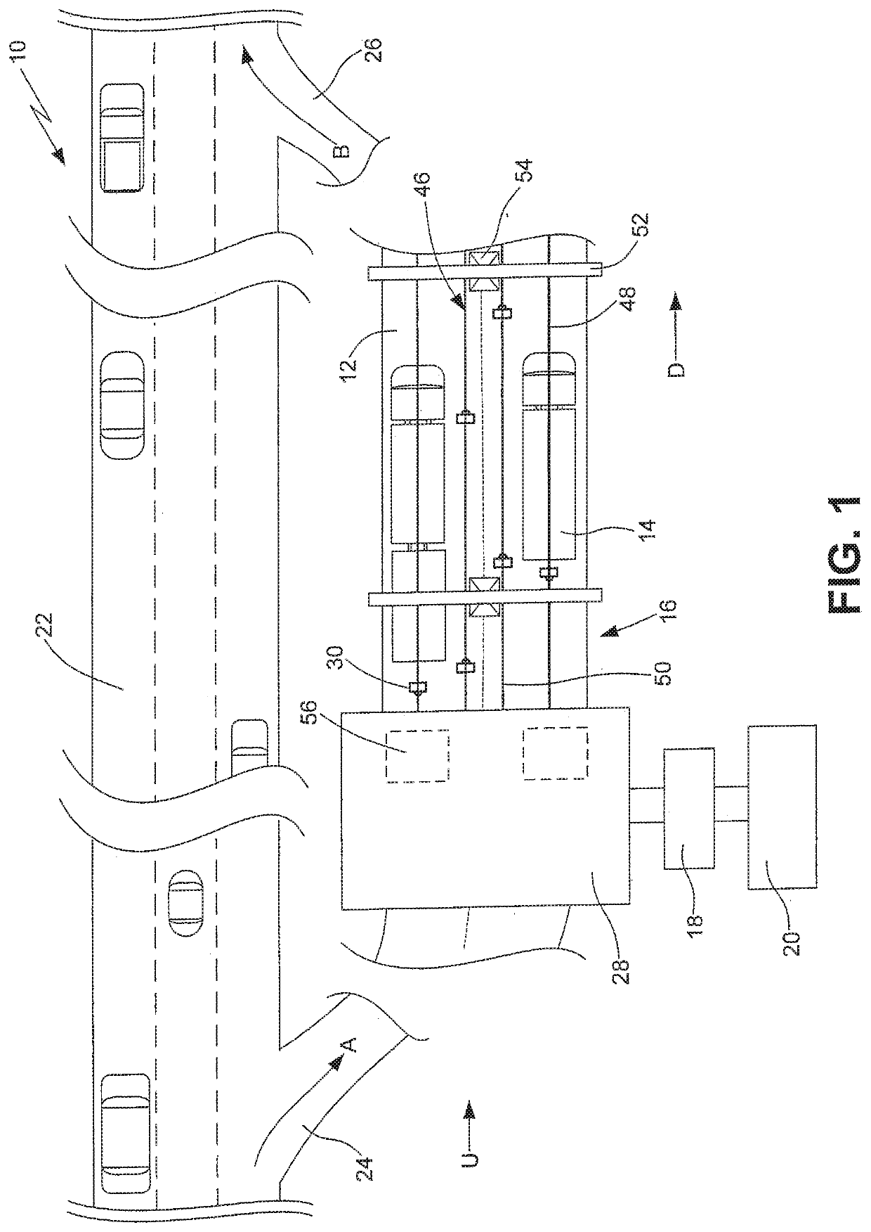
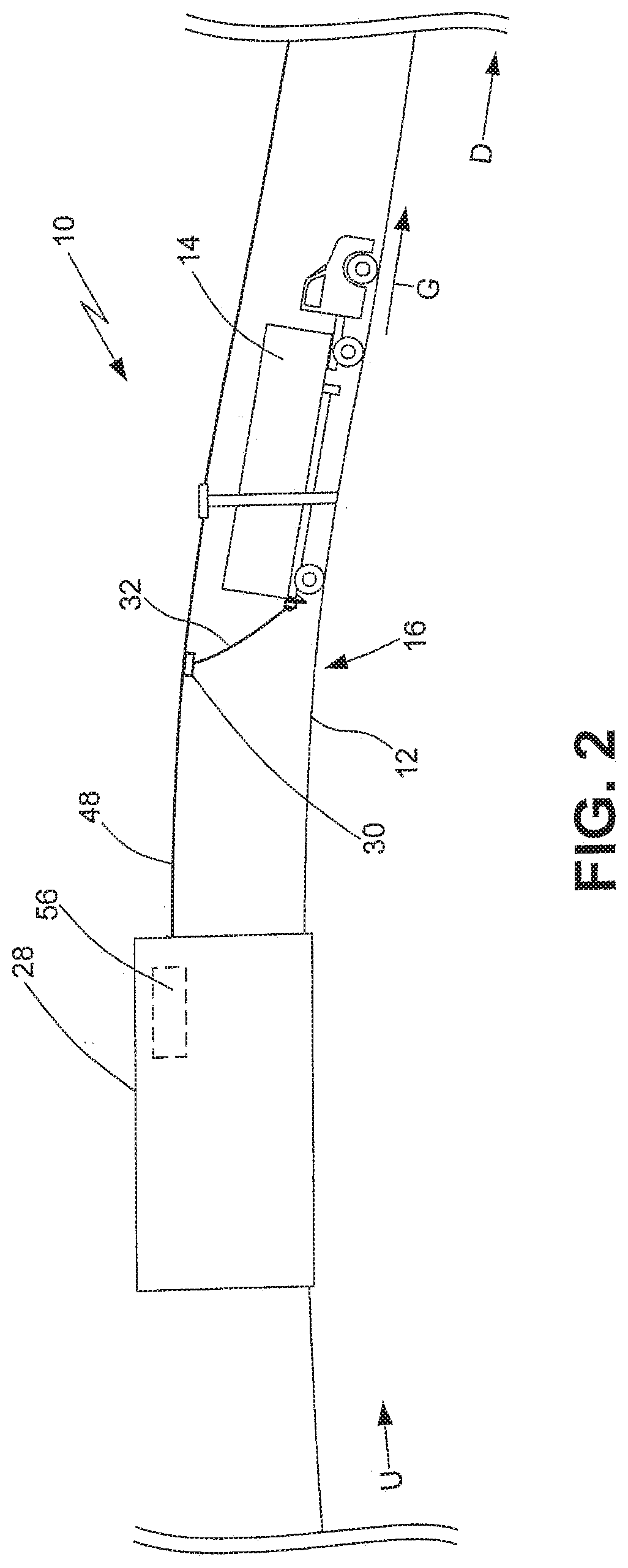
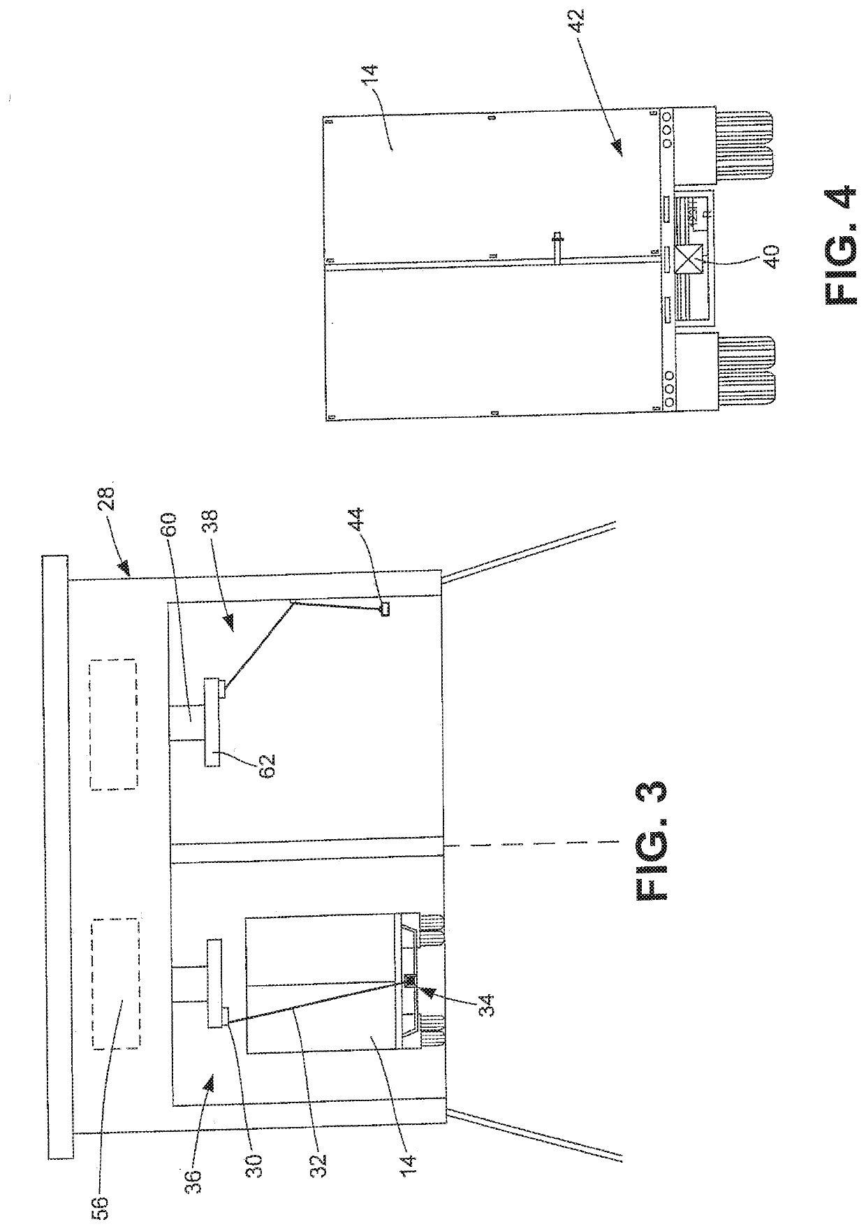
Gravity line power generation system

a gravity line and power generation technology, applied in the direction of motors, dynamo-electric components, dynamo-electric machines, etc., can solve the problems of increasing the cost of electricity, increasing the overall demand for electricity, or being more expensive or otherwise disfavored,

Active Publication Date: 2020-02-13
CRAWFORD RUSSELL WAYNE
View PDF0 Cites 3 Cited by
  • Summary
  • Abstract
  • Description
  • Claims
  • Application Information

AI Technical Summary

Benefits of technology

[0019]In embodiments, the vehicle may be in an unpowered or low-powered mode during step b).

Problems solved by technology

Nonetheless, given the vast array of common devices that run on electrical power (e.g. computers, air conditioning units, audio systems, kitchen appliances, etc.), consumers generally expect that electricity will be available to them whenever it is needed; thus, the overall demand for electricity is rapidly increasing, even as the energy sources most often used to generate it have become less available, more expensive, or otherwise disfavored.
Thus, as demand for electricity increases, so too does demand for fossil fuels and the like, increasing their cost, decreasing their availability, and increasing their impact on the environment.
A well-known limitation of gravity-powered systems is that the one or more weights on which gravitational forces act to create a force imbalance (and, thus, a torque) must first be placed into a position where they will move as a result of gravity; for example, the use of the force of a falling object to operate a machine requires that the object first be placed into a position from which it will fall.
Necessarily, this placement requires an expenditure of energy to lift the object to its resting position, and by the laws of thermodynamics, any system that attempts to utilize the force of gravity as a source of work will consume at least as much energy as it produces if it must return a falling object from an ending position to a starting one.
While a number of prior art systems have sought to utilize this possible source of energy by positioning an apparatus in, on, or along a road or rails, such that the movement of the vehicle over the apparatus operates a mechanism that produces electricity, such systems have generally suffered from mechanical and cost concerns that have limited their practical applicability.

Method used


Image

  • Gravity line power generation system
  • Gravity line power generation system
  • Gravity line power generation system

Examples


Embodiment Construction

[0034]As used herein, the phrases “at least one,”“one or more,”“or,” and “and / or” are open-ended expressions that are both conjunctive and disjunctive in operation. For example, each of the expressions “at least one of A, B and C,”“at least one of A, B, or C,”“one or more of A, B, and C,”“one or more of A, B, or C,”“A, B, and / or C,” and “A, B, or C” means A alone, B alone, C alone, A and B together, A and C together, B and C together, or A, B, and C together.

[0035]As used herein, the term “a” or “an” entity refers to one or more of that entity. As such, the terms “a” (or “an”), “one or more,” and “at least one” can be used interchangeably herein. It is also to be noted that the terms “comprising,”“including,” and “having” can be used interchangeably.

[0036]As used herein, the terms “grade,”“gradient,”“incline,”“pitch,”“slope,” and “tilt” are interchangeable and each refer to an angle of a surface of a landform or other physical feature relative to a horizontal axis or plane. A positi...


PUM


Abstract

A power generation system for the production of electric power or the accomplishment of other work objectives utilizes kinetic energy derived from the action of the force of gravity on a vehicle that is allowed to move along a power generation path having a downward grade. A tether cable connects the vehicle to a tether member that moves along a downhill line in response to the movement of the vehicle along the path, and the movement of the tether member operates a gearing mechanism that operates a machine to accomplish the work objective.

Description

CROSS-REFERENCE TO RELATED APPLICATION[0001]This application claims the benefit under 35 U.S.C. § 119(e) of U.S. Provisional Patent Application 62 / 717,595, filed 10 Aug. 2018, the entirety of which is incorporated herein by reference.FIELD OF THE INVENTION[0002]The present invention relates generally to apparatuses and systems for generating power to perform work, and particularly to apparatuses and systems that utilize gravitational force, such as that resulting from downward movement of a vehicle, to generate power.BACKGROUND OF THE INVENTION[0003]Apparatuses and systems for converting a source of energy to power useful for generating electricity, turning a wheel, operating a machine (e.g. a pump, a grinding wheel, a drill, etc.), or otherwise performing work have been known for many centuries. In ancient times, the sources of energy most commonly used in such apparatuses and systems were people, animals, moving water, or wind, while in the modern era such apparatuses and systems,...

Claims


Application Information

Patent Timeline
Patent Type & Authority Applications(United States)
IPC IPC(8): H02K7/18F03G3/00
CPCF03G3/00H02K7/1853H02K7/1861
Inventor CRAWFORD, RUSSELL WAYNE
Owner CRAWFORD RUSSELL WAYNE
Why Eureka
Try Eureka