Synthesis Path For Transforming Concurrent Programs Into Hardware Deployable on FPGA-Based Cloud Infrastructures

Active Publication Date: 2020-02-20
RECONFIGURE IO LTD
View PDF0 Cites 8 Cited by
  • Summary
  • Abstract
  • Description
  • Claims
  • Application Information

AI Technical Summary

Benefits of technology

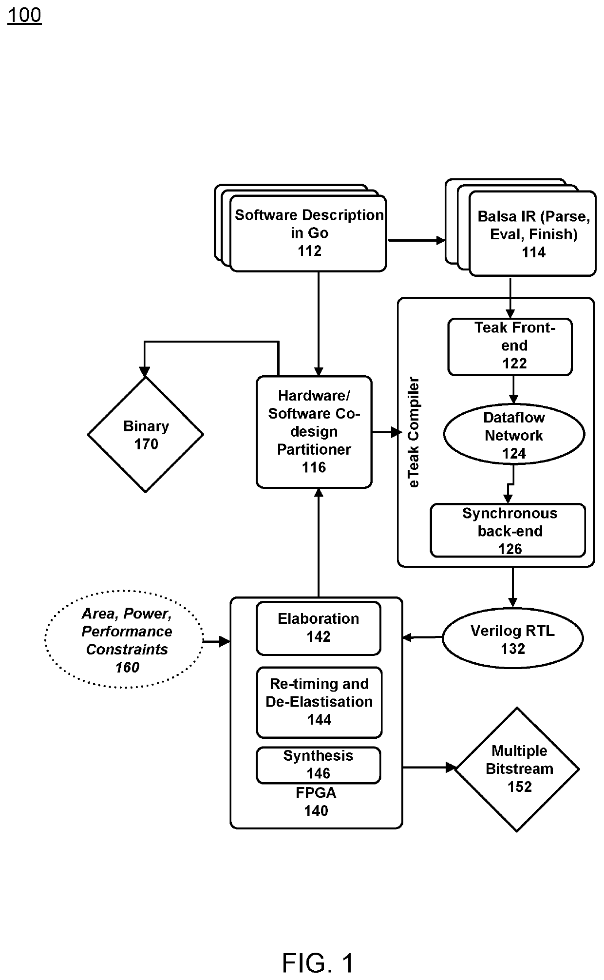
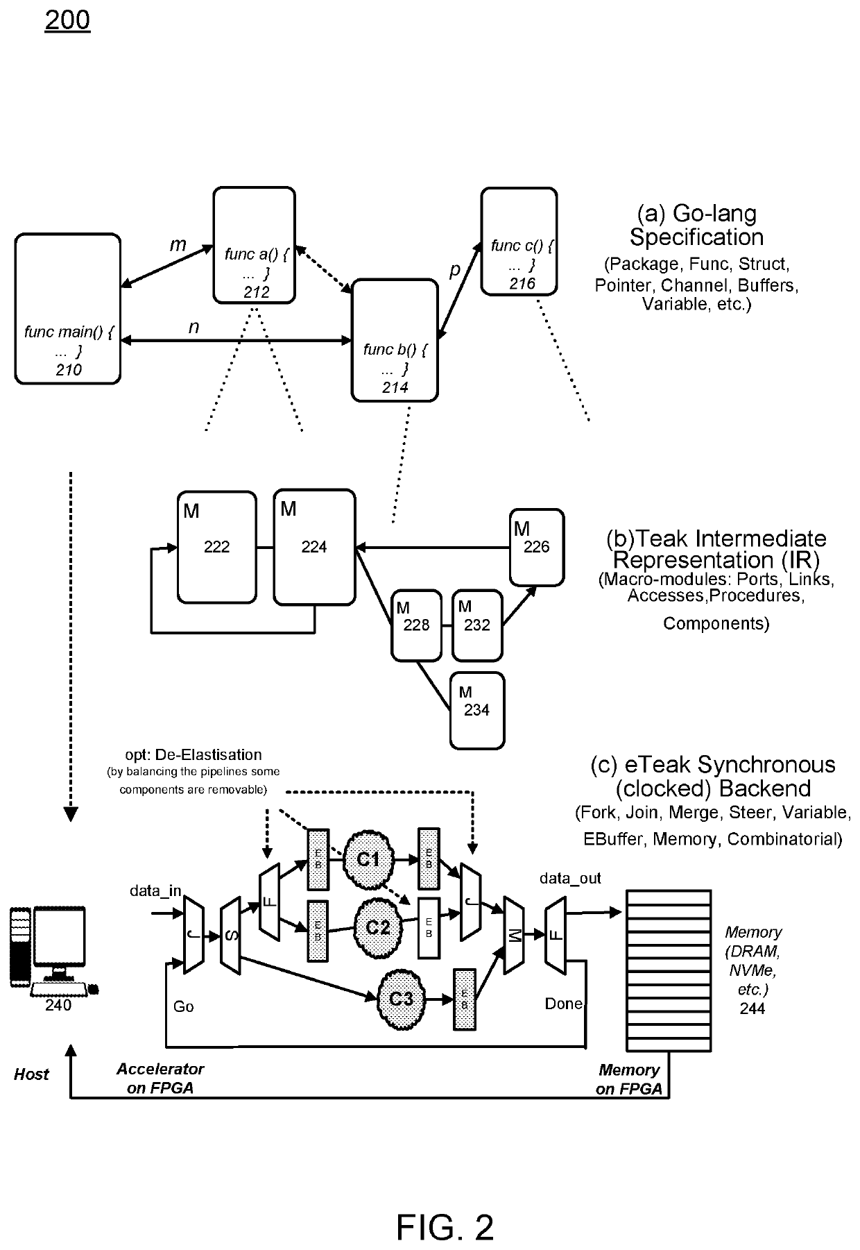
[0011]One example embodiment of the present application may provide a method that includes creating synchronous hardware accelerators from concurrent asynchronous programs at software level, the method may include at least one of obtaining input as software instructions describing concurrent behavior via a model of communicating sequential processes (CSP) of message exchange between concurrent processes performed via channels, mapping, on a computing device, each of the concurrent processes to synchronous dataflow primitives, comprising at least one of join, fork, merge, steer, variable, and arbiter, producing a clocked digital logic description for upload to one or more field programmable gate array (FPGA) devices, performing primitive remapping of the output design for throughput, clock rate and resource usage via retiming, and creating an annotated graph of the input software description for debugging of concurrent code for the field FPGA devices.
[0012]Another example embodiment may include an apparatus configured to create synchronous hardware accelerators from concurrent asynchronous programs at software level, the apparatus may include a processor configured to obtain input as software instructions describing concurrent behavior via a model of communicating sequential processes (CSP) of message exchange between concurrent processes performed via channels, map each of the concurrent processes to synchronous dataflow primitives, comprising at lea

Problems solved by technology

However, integrated software applications with middleware and hardware platforms continues to be limited and thus leaves the developers without the resources needed to work with certain hardware development platforms such as FPGAs.
IT departments trying to utilize this technology face barriers including low-level languages and representat

Method used


Image

  • Synthesis Path For Transforming Concurrent Programs Into Hardware Deployable on FPGA-Based Cloud Infrastructures
  • Synthesis Path For Transforming Concurrent Programs Into Hardware Deployable on FPGA-Based Cloud Infrastructures
  • Synthesis Path For Transforming Concurrent Programs Into Hardware Deployable on FPGA-Based Cloud Infrastructures

Examples


Embodiment Construction

[0021]It will be readily understood that the components of the present application, as generally described and illustrated in the figures herein, may be arranged and designed in a wide variety of different configurations. Thus, the following detailed description of the embodiments of a method, apparatus, and system, as represented in the attached figures, is not intended to limit the scope of the application as claimed, but is merely representative of selected embodiments of the application.

[0022]The features, structures, or characteristics of the application described throughout this specification may be combined in any suitable manner in one or more embodiments. For example, the usage of the phrases “example embodiments”, “some embodiments”, or other similar language, throughout this specification refers to the fact that a particular feature, structure, or characteristic described in connection with the embodiment may be included in at least one embodiment of the present applicati...


PUM


Abstract

Exploiting FPGAs for acceleration may be performed by transforming concurrent programs. One example mode of operation may provide one or more of creating synchronous hardware accelerators from concurrent asynchronous programs at software level, by obtaining input as software instructions describing concurrent behavior via a model of communicating sequential processes (CSP) of message exchange between concurrent processes performed via channels, mapping, on a computing device, each of the concurrent processes to synchronous dataflow primitives, comprising at least one of join, fork, merge, steer, variable, and arbiter, producing a clocked digital logic description for upload to one or more field programmable gate array (FPGA) devices, performing primitive remapping of the output design for throughput, clock rate and resource usage via retiming, and creating an annotated graph of the input software description for debugging of concurrent code for the field FPGA devices.

Description

CROSS-REFERENCE TO RELATED APPLICATION[0001]This application is related to previously filed provisional patent application No. 62 / 412,376 entitled ‘SYNTHESIS PATH FOR TRANSFORMING PROGRAMS INTO HARDWARE DEPLOYABLE ON FPGA-BASED CLOUD INFRASTRUCTURES’, which was filed on Oct. 25, 2016, the entire contents of which are hereby incorporated by reference in their entirety.TECHNICAL FIELD OF THE APPLICATION[0002]This application relates to software and hardware integration and more specifically adapting a software development interface for FPGA developments.BACKGROUND OF THE APPLICATION[0003]Conventionally, the recent advances in concurrent programming and the formal model of communicating sequential processes (CSP) has gained popularity. The CSP model allows software designers to implement scalable concurrent software systems. However, integrated software applications with middleware and hardware platforms continues to be limited and thus leaves the developers without the resources neede...

Claims


Application Information

Patent Timeline
IPC IPC(8): G06F9/52G06F9/54G06F9/50G06F9/48G06F9/38
CPCG06F9/52G06F9/3867G06F9/48G06F9/546G06F9/5027G06F11/3628G06F11/3648G06F30/331
Inventor MAMAGHANI, MAHDI JELODARITAYLOR, ROBERT JAMES
Owner RECONFIGURE IO LTD
Why Eureka
Try Eureka