Display panel and method of improving display quality thereof

a technology of display panel and display panel, which is applied in the direction of electrical equipment, semiconductor devices, instruments, etc., can solve the problems of uneven brightness in different areas of the display panel, and achieve the effect of improving the display quality of the display panel, and reducing the channel width of the first driving transistor

Active Publication Date: 2020-02-20
HANNSTAR DISPLAY CORPORATION
View PDF0 Cites 7 Cited by
  • Summary
  • Abstract
  • Description
  • Claims
  • Application Information

AI Technical Summary

Benefits of technology

[0007]The present invention further provides a method of improving the display quality of a display panel, which includes the following steps. First, a layout design of a display panel is provided, which includes a substrate, a plurality of first sub pixels, a plurality of second sub pixels, a first gate driving unit and a second gate driving unit. The substrate has a surface, wherein the surface includes a display region and a peripheral region disposed on at least one side of the display region. The display region includes a first area and a second area, wherein the first area has a first scan line and the second area has a second scan line. The first sub pixels are disposed in the first area, wherein at least a portion of the first sub pixels are electrically connected to the first scan line. The second sub pixels are disposed in the second area, wherein at least a portion of the second sub pixels are electrically connected to the second scan line. The first gate driving unit is disposed in the peripheral region, wherein the first gate driving unit has a first driving transistor, the first gate driving unit is electrically connected to the first scan line, and the portion of the first sub pixels electrically connected to the first scan line are driven through the first scan line by the first gate driving unit. The second gate driving unit is disposed in the peripheral region, wherein the second gate driving unit has a second driving transistor, the second gate driving unit is electrically connected to the second scan line, the portion of the second sub pixels electrically connected to the second scan line are driven through the second scan line by the second gate driving unit, and the number of the first sub pixels driven by the first gate driving unit are less than the number of the second sub pixels driven by the second gate driving unit. Next, the RC loading of the first scan line and the RC loading of the second scan line are estimated. Then, a first driving unit modifying step is performed, including modifying a channel width of the first driving transistor according to an estimation result of the RC loadings of the first scan line and the second scan line. Next, a simulation on the first gate driving unit and the second gate driving unit is performed to obtain a plurality of signal output waveforms of the first gate driving unit and the second gate driving unit. Then, a second driving unit modifying step is performed, including modifying the channel width of the first driving transistor according to the signal output waveforms of the first gate driving unit and the second gate driving unit.
[0008]In the display panel and method of improving the display quality of the display panel according to the present invention, the channel width of the first driving transistor is reduced according to the RC loading of the first scan line, such that the driving power of the first gate driving unit is reduced, and the driving power of each of the first gate driving units may match the RC loading of the first scan line corresponding to each of the first gate driving units. Therefore, the transmission quality of the scanning signals in the first area and the second area may be consistent, and the problem of uneven brightness in different areas of the display panel is improved, which improves the display quality.

Problems solved by technology

When the same scanning signal is input to pixels in different areas, a phenomenon where the gray levels are not consistent may occur, thereby causing uneven brightness indifferent areas of the display panel.

Method used


Image

  • Display panel and method of improving display quality thereof
  • Display panel and method of improving display quality thereof
  • Display panel and method of improving display quality thereof

Examples


Embodiment Construction

[0023]To provide a better understanding of the present invention to those skilled in the technology, embodiments will be detailed as follows. The embodiments of the present invention are illustrated in the accompanying drawings to elaborate on the contents and effects to be achieved. It should be noted that the drawings are simplified schematics, and therefore show only the components and combinations associated with the present invention, so as to provide a clearer description of the basic architecture or method of implementation. The components would be complex in reality. In addition, for ease of explanation, the components shown in the drawings may not represent their actual number, shape, and dimensions; details can be adjusted according to design requirements.

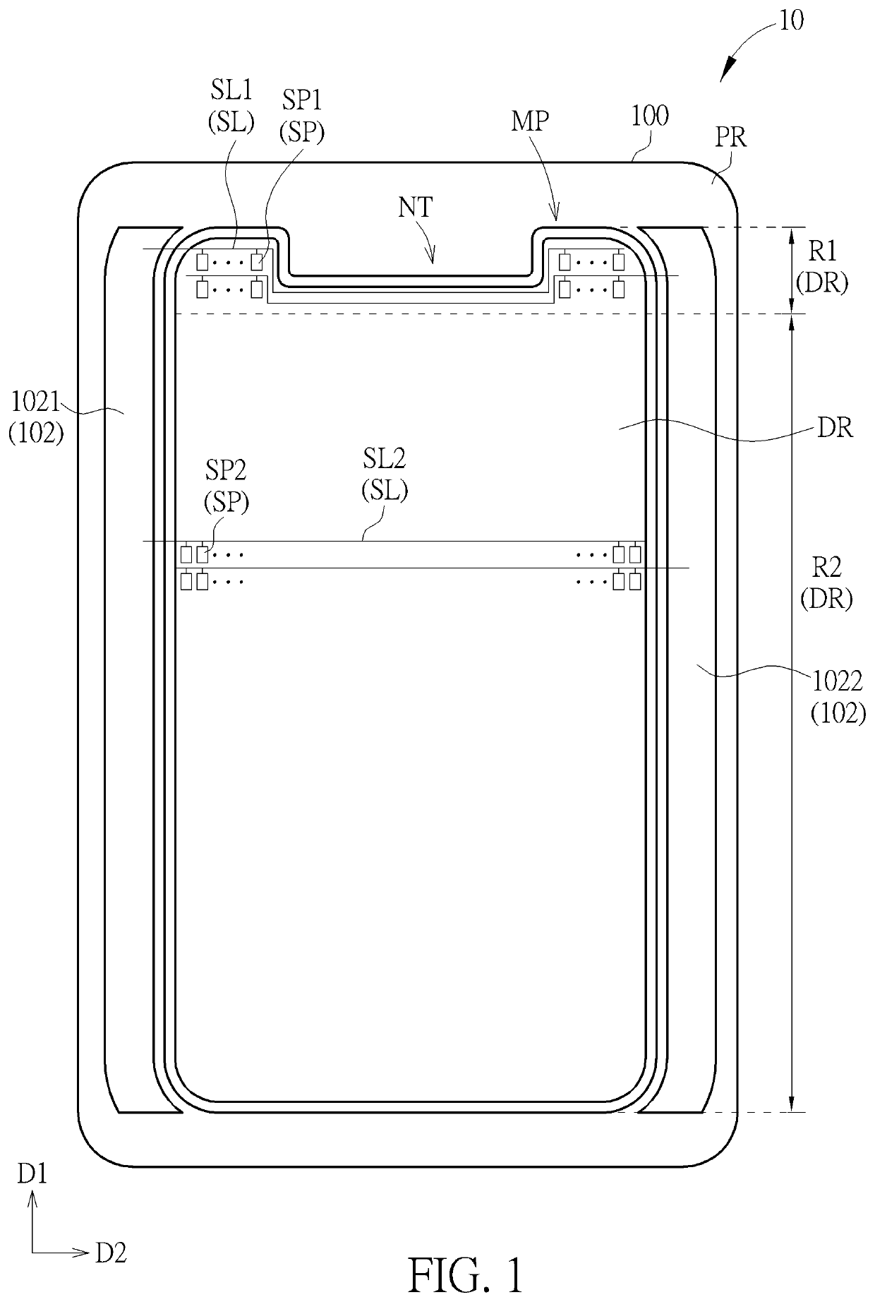
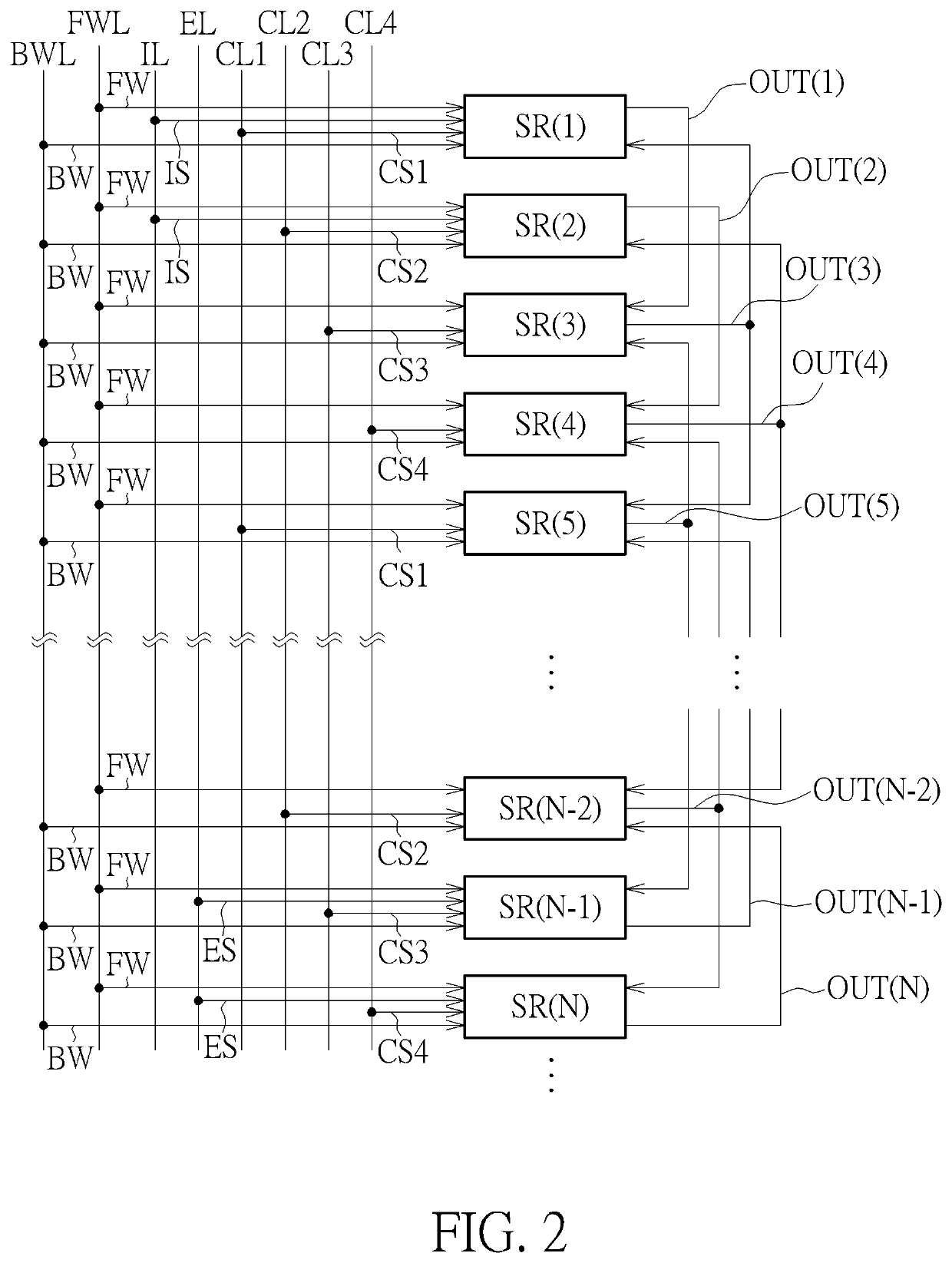
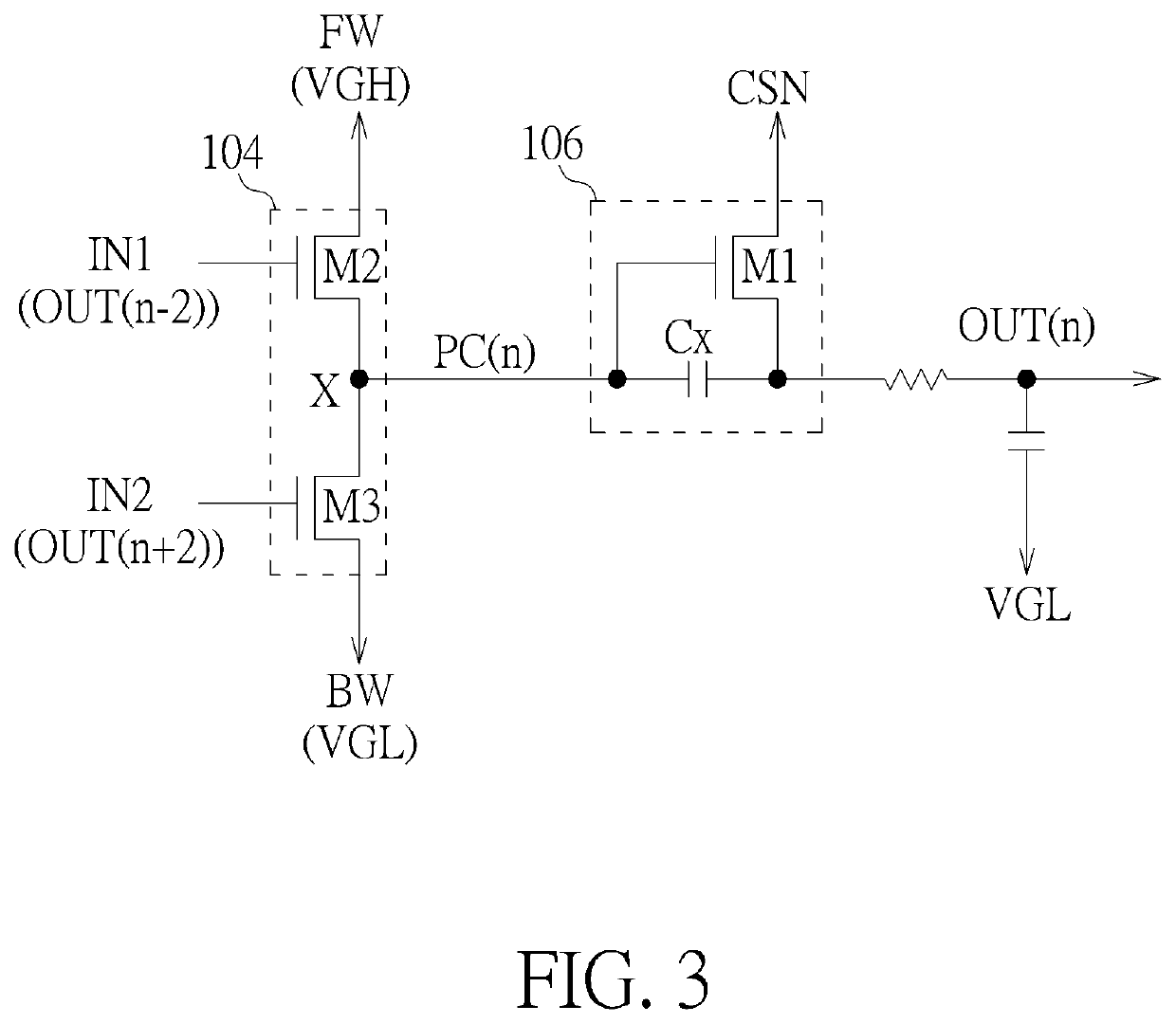
[0024]Referring to FIG. 1 to FIG. 9, FIG. 1 is a schematic diagram illustrating a top view of a display panel according to a first embodiment of the present invention, FIG. 2 is a schematic diagram illustrating a gate dri...


PUM


Abstract

A display panel includes a substrate having a display region and a peripheral region, first and second sub pixels, first and second gate driving units. The display region includes a first area having first scan lines and first sub pixels and a second area having second scan lines and second sub pixels. A portion of the first sub pixels and a portion of the second sub pixels are respectively electrically connected to the first and second scan line. The first gate driving unit includes a first driving transistor. The second gate driving unit includes a second driving transistor. The number of the first sub pixels driven by the first gate driving unit is less than the number of the second sub pixels driven by the second gate driving unit. The channel width of the first driving transistor is less than the channel width of the second driving transistor.

Description

CROSS REFERENCE TO RELATED APPLICATION[0001]This application claims priority of China Application No. 201810922464.6, filed on Aug. 14, 2018. The entirety of the above-mentioned patent application is incorporated by reference herein and made a part of this specification.BACKGROUND OF THE INVENTION1. Field of the Invention[0002]The present invention relates to a display panel and a method of improving the display quality of a display panel, and more particularly, to a display panel and a method of improving the display quality of a display panel by improving undesirable gray levels between areas with different shapes in a display region.2. Description of the Prior Art[0003]A display panel is formed by two substrates and a plurality of layers with various electrical components disposed between the two substrates. Since display panels are thin and light, have low power consumption and no radiation pollution, they are widely used in various portable or wearable electronic products such ...

Claims


Application Information

Patent Timeline
Patent Type & Authority Applications(United States)
IPC IPC(8): G09G3/20
CPCG09G3/20G09G2300/0439G09G2320/0626G09G2300/0426G09G2320/0233G09G2310/0267H01L27/1214H01L27/124H10K59/00H10K59/1216H10K59/12H10K59/131G09G2320/0223G09G2310/0286G09G2310/0232G09G3/3677G09G3/3266
Inventor LIU, HSUAN-CHENCHAN, CHIEN-TINGCHANG, CHUNG-LIN
Owner HANNSTAR DISPLAY CORPORATION
Why Eureka
Try Eureka