Guide device suitable for performing temporomandibular joint arthroscopy

a technology of temporomandibular joint and guide device, which is applied in the field of surgical guides to achieve the effect of accurate insertion and positioning

Active Publication Date: 2020-02-27
TEL HASHOMER MEDICAL RES INFRASTRUCTURE & SERVICES
View PDF0 Cites 7 Cited by
  • Summary
  • Abstract
  • Description
  • Claims
  • Application Information

AI Technical Summary

Benefits of technology

[0010]Some embodiments of the invention relate to a guide device suitable for assisting in performing a TMJ arthroscopy procedure. In some embodiments, the guide device allows accurate insertion and positioning of a cannula (e.g., that constitutes the working channel) relative to a first cannula (that constitutes an irrigation channel). Some embodiments of the guide device of the invention are configured to position one channel (e.g., the working channel) at an angle different from perpendicular to the second chan

Problems solved by technology

For example, to access the TMJ from a direction that is surgically preferred but would not be ordinarily

Method used


Image

  • Guide device suitable for performing temporomandibular joint arthroscopy
  • Guide device suitable for performing temporomandibular joint arthroscopy
  • Guide device suitable for performing temporomandibular joint arthroscopy

Examples


first embodiment

of the Device

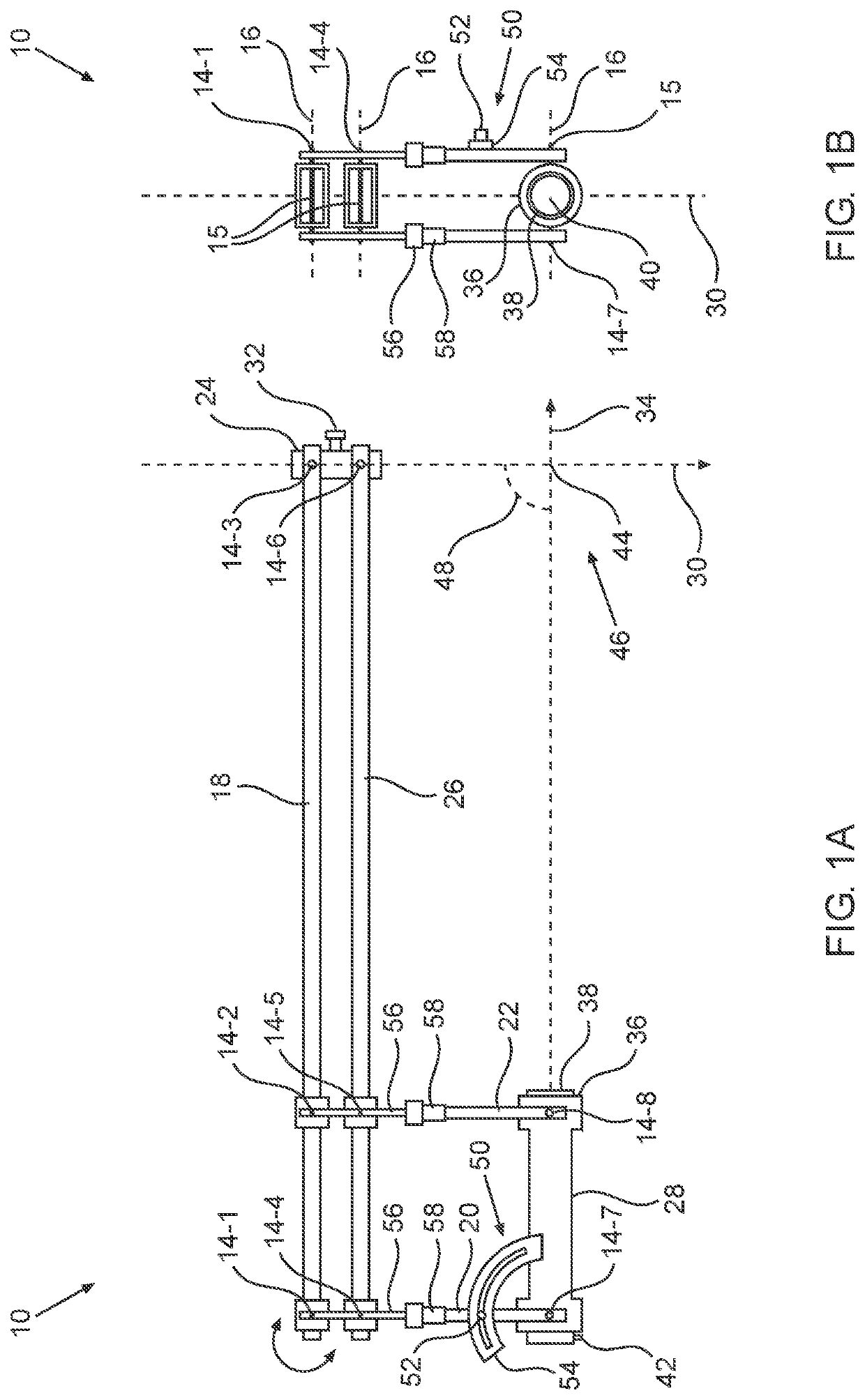
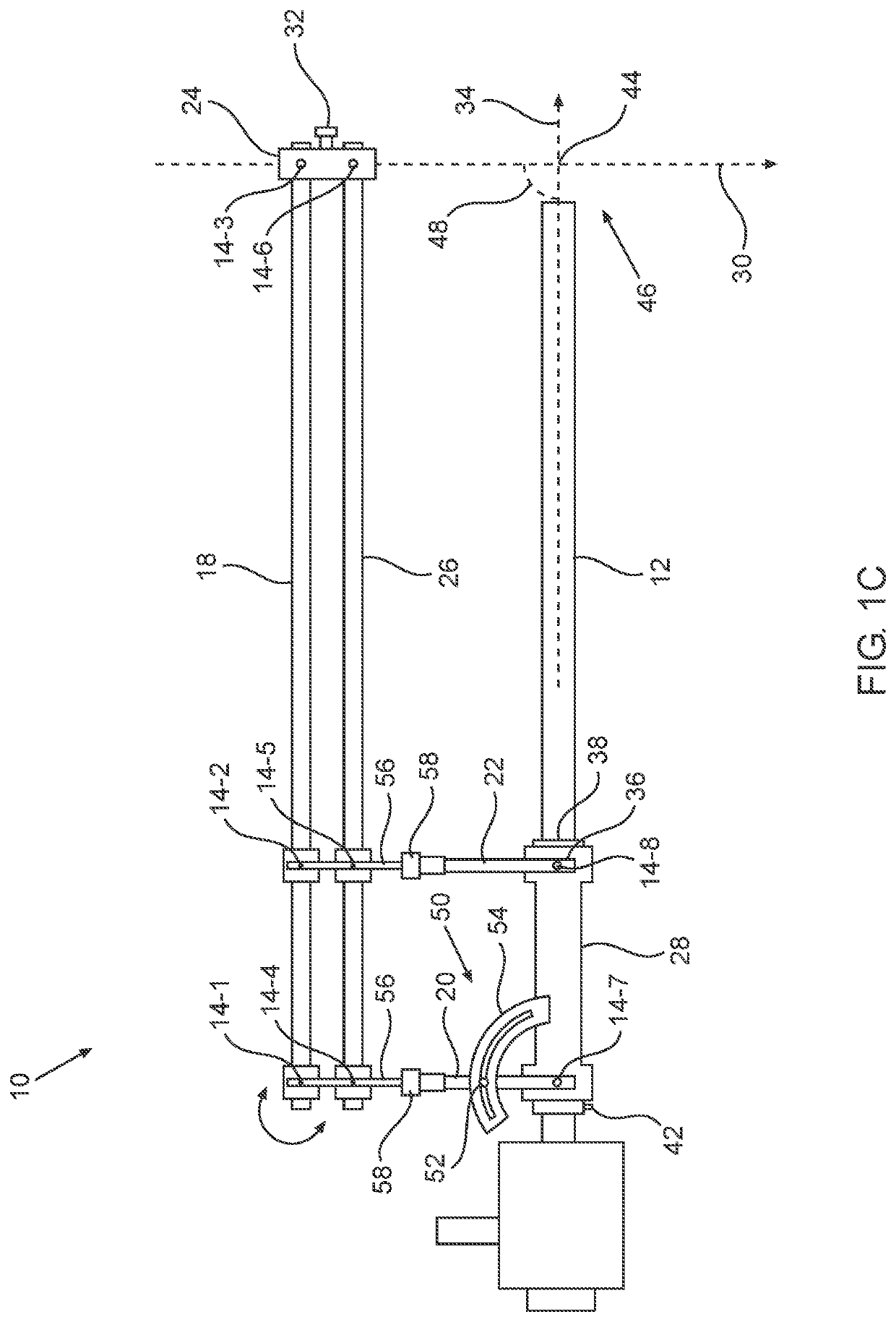
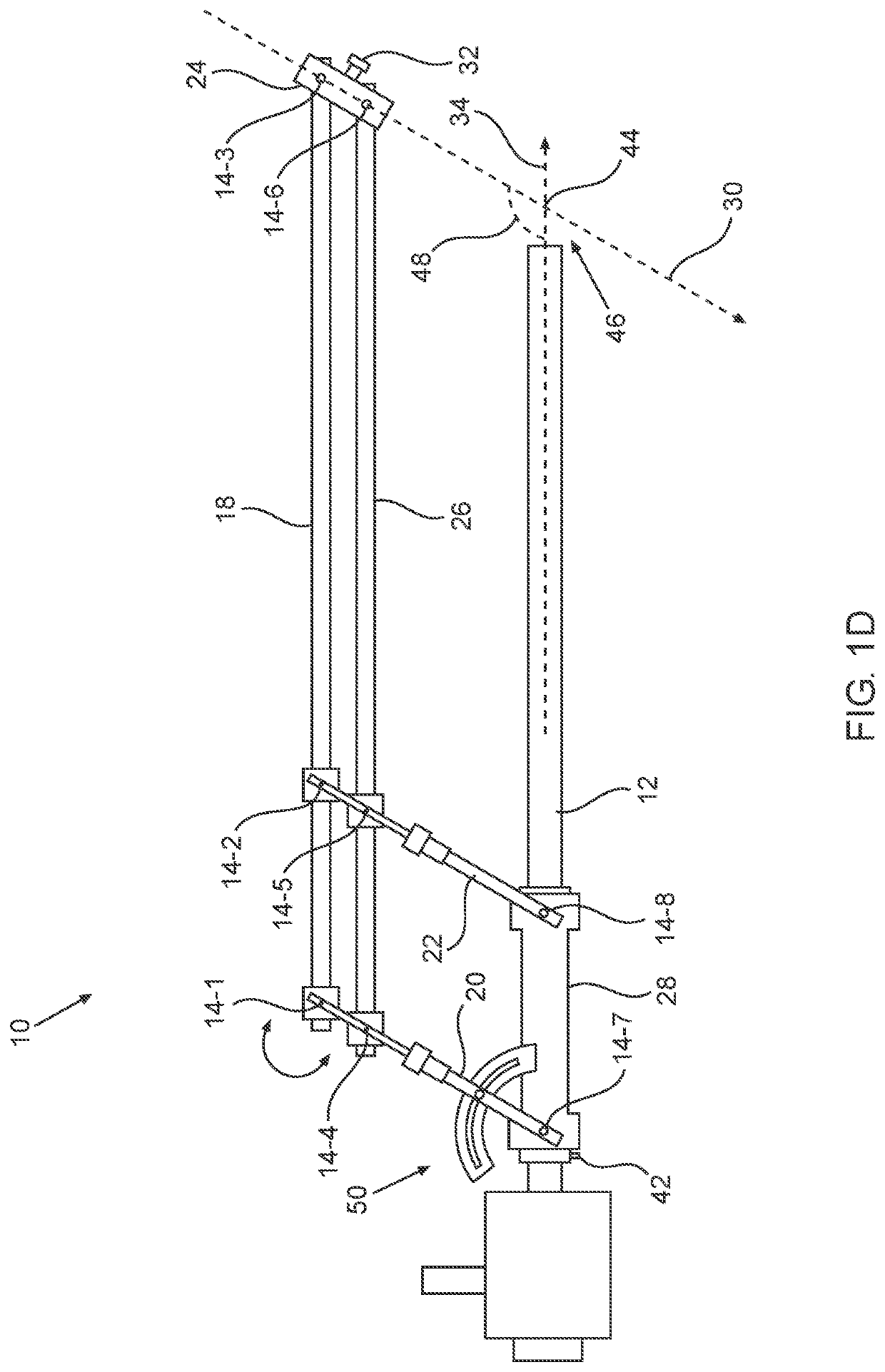
[0073]A first exemplary embodiment of a guide device according to the teachings herein, device 10, is schematically depicted in FIGS. 1A to 1D.

[0074]To avoid clutter of the figures that will reduce clarity, not all components are labeled in all of the figures.

[0075]FIGS. 1A to 1D schematically depict a first exemplary embodiment of a guide device according to the teachings herein:

[0076]in FIG. 1A in side view in a configuration where the working channel axis is perpendicular to the irrigation channel axis;

[0077]in FIG. 1B in view from the back;

[0078]in FIG. 1C in side view with a physically associated irrigation channel 12 in a conformation where the working part axis is perpendicular to the irrigation channel axis; and

[0079]in FIG. 1D in side view with a physically associated irrigation channel 12 in a conformation where the working part axis is not perpendicular to the irrigation channel axis.

[0080]The components of device 10 are made of autoclavable surgical stainles...

second embodiment

of the Device

[0127]A second exemplary embodiment of a guide device according to the teachings herein, device 60, is schematically depicted in FIG. 2 in side view. Most of the components and construction, as well as the use of device 60 are substantially the same as of device 10 so for the sake of brevity will not be discussed further.

[0128]A notable difference between device 60 and device 10 is the construction of working channel holder 24 and of irrigation channel holder 28.

[0129]In device 10, working channel holder 24 directly rigidly connects the third and sixth revolute joints 14-3 and 14-6 respectively, whether or not there is a working channel held therein.

[0130]In contrast, in device 60, working channel holder 24 comprises two physically separate working channel holder parts, first part 24a connected to third revolute joint 14-3 and second part 24b connected to sixth revolute joint 14-6. In device 60, third and sixth revolute joints are directly rigidly connected only when a ...

third embodiment

of the Device

[0133]A third exemplary embodiment of a guide device according to the teachings herein, device 62, is schematically depicted in FIG. 3A in side view and in FIG. 3B in view from the back. Most of the components and construction, as well as the use, of device 62 are substantially the same as of device 10 so for the sake of brevity will not be discussed further.

[0134]A first difference is that device 62 is devoid of a working channel lock.

[0135]As noted above, in device 10, axes of rotation 16 of revolute joints 14-n are perpendicular to a plane that includes both working channel axis 30 and irrigation channel axis 34.

[0136]In contrast, in device 62, although axes of rotation 16 of revolute joints 14-n are substantially perpendicular to a plane that includes irrigation channel axis 34, axes of rotation 16 of revolute joints 14-n are not perpendicular to a plane that includes both working channel axis 30 and irrigation channel axis 34. In device 62, working channel holder 2...


PUM


Abstract

A guide device for TMJ arthroscopy including one or more pairs of arms pivotly connected at one end to a working cannula holder and defining a working cannula axis; and at the opposite end to at one or more arms via one or more pivot connections to form with the arm one or more adjustable parallelograms, an end of the arm is connected to an irrigation cannula holder defining an irrigation cannula axis, the irrigation cannula axis intersecting with the working cannula axis at an intersection, intersection and one or more of the pivot connections between connecting the arms are located at opposing vertices of one or more of the adjustable parallelograms.

Description

FIELD AND BACKGROUND OF THE INVENTION[0001]The invention, in some embodiments, relates to the field of surgical guides, and more specifically, to a guide device suitable for assisting in performing a TMJ arthroscopy procedure.[0002]TMJ arthroscopy is a minimally-invasive surgical procedure that is performed on the TMJ (Temporo-Mandibular Joint, the jaw joint).[0003]In a first step, a surgeon pushes a first cannula (typically with the help of a trocar) through the skin and other tissue to enter the TMJ to define an irrigation aperture channel. Once the distal tip of the first cannula is properly positioned, an irrigation device is inserted into the TMJ through the first cannula and used to force fluid such as saline into the TMJ to cause hydrodistension of the TMJ, forming a relatively large fluid-filled space. The volume of the fluid-filled space is initially about 1 ml, but typically increases during a TMJ arthroscopy procedure to between 5 ml and 8 ml.[0004]A second cannula (typic...

Claims


Application Information

Patent Timeline
IPC IPC(8): A61B17/34A61B90/57
CPCA61B17/3423A61B2017/00424A61B17/3403A61B2017/3407A61B2090/506A61B1/317A61B90/57A61B1/01A61B17/3421A61B90/50A61B2090/034
Inventor ABBOUD, WASEEM
Owner TEL HASHOMER MEDICAL RES INFRASTRUCTURE & SERVICES
Why Eureka
Try Eureka