Method and arrangement to detect an oil leakage between sections of a hydraulic cylinder

Active Publication Date: 2020-02-27
SIEMENS GAMESA RENEWABLE ENERGY AS
View PDF0 Cites 0 Cited by
  • Summary
  • Abstract
  • Description
  • Claims
  • Application Information

AI Technical Summary

Benefits of technology

The invention helps prevent unnecessary maintenance visits and operational stops in wind turbines, which saves money, especially for offshore wind turbines. It also allows for more frequent checking of troubled parts, increasing system security and lifespan.

Problems solved by technology

The failure results from a leakage of hydraulic oil.
Hydraulic oil might leak externally, leaving the hydraulic cylinder and the hydraulic system itself.
Hydraulic oil even might leak inside the hydraulic cylinder, which is known as internal leakage: i.e. if there is a leakage at the movable piston hydraulic oil might be transferred between the first and the second section in an uncontrolled manner.
The internal leakage often evolves over time and results in an increased pumping and circulation of oil in the hydraulic system, which might comprise the cylinder, an oil-reservoir, oil supply connections, a pump, valves, etc.
An internal leakage cannot be detected easily as the hydraulic oil stays inside the hydraulic system and cannot be detected by checking the level of the hydraulic oil in the oil-reservoir for example.
The effects of oil leakages will increase over time and will finally result in an operational error, which is reported to a control of the wind turbine.
Especially for offshore wind turbines, showing a guaranteed lifetime of 25 years or more, maintenance work for hydraulic components is a huge and costly problem.
It was found that such wind turbines might require in a worst-case scenario two hydraulic cylinder exchanges over the lifetime of the wind turbine.
Due to the harsh offshore environment service time is restricted and limited while equipment, which is needed for the service work, might be expensive as well.
A wind turbine often starts to report errors according to this sequence:Report: pumping time becomes prolonged,Report: temperature of the hydraulic oil starts to increase, and finally anReport: an unwanted pitch tracking occurs during the wind turbine operation.
Thus, the leakage in the cylinder is detected quite early and before severe damages of the cylinder took place.
This results in considerable cost savings especially for offshore wind turbines.
The cylinder wear depends on the site of the wind turbine thus turbulences might affect the lifetime negatively.

Method used


Image

  • Method and arrangement to detect an oil leakage between sections of a hydraulic cylinder
  • Method and arrangement to detect an oil leakage between sections of a hydraulic cylinder

Examples


Embodiment Construction

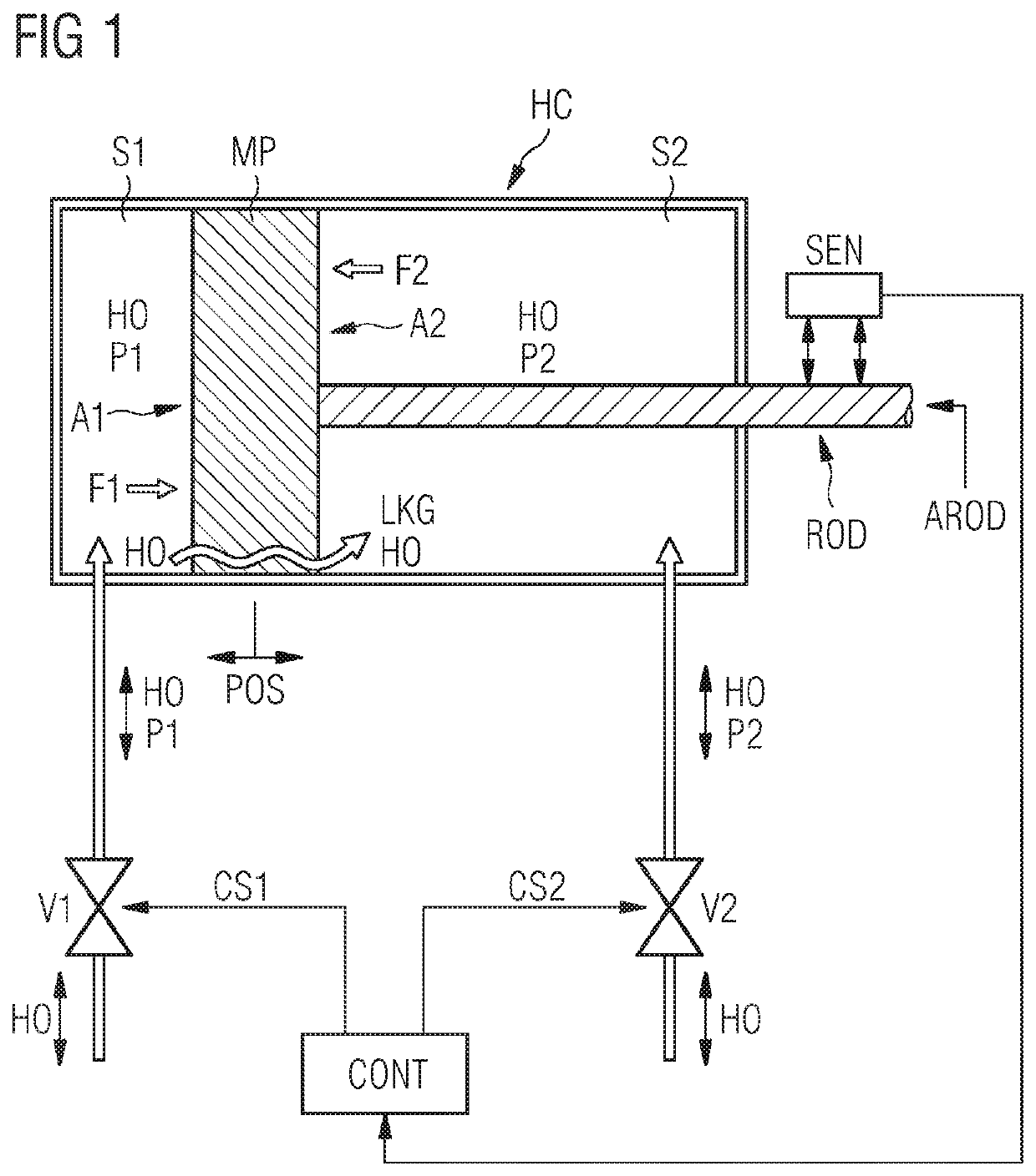
[0053]FIG. 1 shows the arrangement.

[0054]A hydraulic cylinder HC comprises a first section S1, while hydraulic oil HO is provided in and out of the first section S1 by a predefined first pressure P1.

[0055]The hydraulic cylinder HC even comprises a second section S2, while hydraulic oil HO is provided in and out of the second section S2 by a predefined second pressure P2.

[0056]The hydraulic cylinder HC comprises a movable piston MP, which is arranged between the first section S1 and the second section S2 in a way that the movable piston MP changes its position POS between the sections S1 and S2.

[0057]The hydraulic oil HO is applied to these sections S1 and S2 thus respective forces F1 and F2 are created.

[0058]A first force F1 is created at the first section S1 according to this formula:

F1=P1*A1.

[0059]P1 is the first pressure at the first section S1, which acts on a first cross sectional area A1 of the movable piston MP.

[0060]A second force F2 is created at the second section S2 accor...


PUM


Abstract

Provided is an arrangement and a method to detect an oil leakage between a first section and a second section of a hydraulic cylinder. A movable piston is arranged between the first and second section in a way that the piston changes position between the sections. The change in position is done in dependency of a difference between a first force, which acts at the first section on a first cross sectional area of the piston, and a second force, which acts at the second section on a second cross sectional area of the piston. The first section comprises hydraulic oil with a predefined first pressure, while the first force is calculated based on this pressure and based on the first area. The second section comprises hydraulic oil with a predefined second pressure, while the second force is calculated based on this pressure and based on the second area.

Description

CROSS-REFERENCE TO RELATED APPLICATIONS[0001]This application claims priority to PCT Application No. PCT / EP2017 / 080462, having a filing date of Nov. 24, 2017, which is based on German Application No. 10 2017 203 049.6, having a filing date of Feb. 24, 2017, the entire contents both of which are hereby incorporated by reference.FIELD OF TECHNOLOGY[0002]The following refers to an arrangement and to a method to detect an oil leakage between a first section of a hydraulic cylinder and a second section of the hydraulic cylinder. The hydraulic cylinder is used in a hydraulic pitch drive system of a wind turbine.BACKGROUND[0003]Modern wind turbines are showing a number of three rotor blades, which are rotating around a horizontal axis of rotation. The rotor blades are connected with an electrical generator to convert wind energy into electrical energy.[0004]Each rotor blade can be aligned into the incoming wind by typically two hydraulic cylinders, being part of a hydraulic pitch drive sys...

Claims


Application Information

Patent Timeline
IPC IPC(8): F15B19/00F03D17/00F15B20/00
CPCF15B20/005F15B19/005F03D17/00F15B2211/7656F03D7/0228F05B2270/604F15B2211/3057F15B2211/6336F15B2211/864F15B2211/87Y02E10/72
Inventor NIELSEN, LARS HOLM
Owner SIEMENS GAMESA RENEWABLE ENERGY AS
Why Eureka
Try Eureka