System and Method for Determining the Parameters of a Controller

a controller and parameter technology, applied in the field of system and method for determining the parameters of the controller, can solve problems such as stepped excitation, and achieve the effect of facilitating the use of a model slave controller as a controller

Active Publication Date: 2020-02-27
SIEMENS AG
View PDF0 Cites 2 Cited by
  • Summary
  • Abstract
  • Description
  • Claims
  • Application Information

AI Technical Summary

Benefits of technology

The invention provides a system and method for automatically determining the parameters of a controller for a controlled system. This makes it easier to use a model slave controller without special expertise. The system uses a master controller in the pilot control process to guide changes in desired value to the controller, reducing the likelihood of the controller hitting its manipulated variable limitation. The system also takes into account the dead time in the controlled system by using a sub-model without dead time and a dead time model connected downstream of the linear sub-model in a series circuit. This allows for optimal command behavior and optimal disturbance behavior in the case of controlled systems with dead time.

Problems solved by technology

This results in a stepped excitation of the model control loop located in the pilot control process.

Method used


Image

  • System and Method for Determining the Parameters of a Controller
  • System and Method for Determining the Parameters of a Controller
  • System and Method for Determining the Parameters of a Controller

Examples


Embodiment Construction

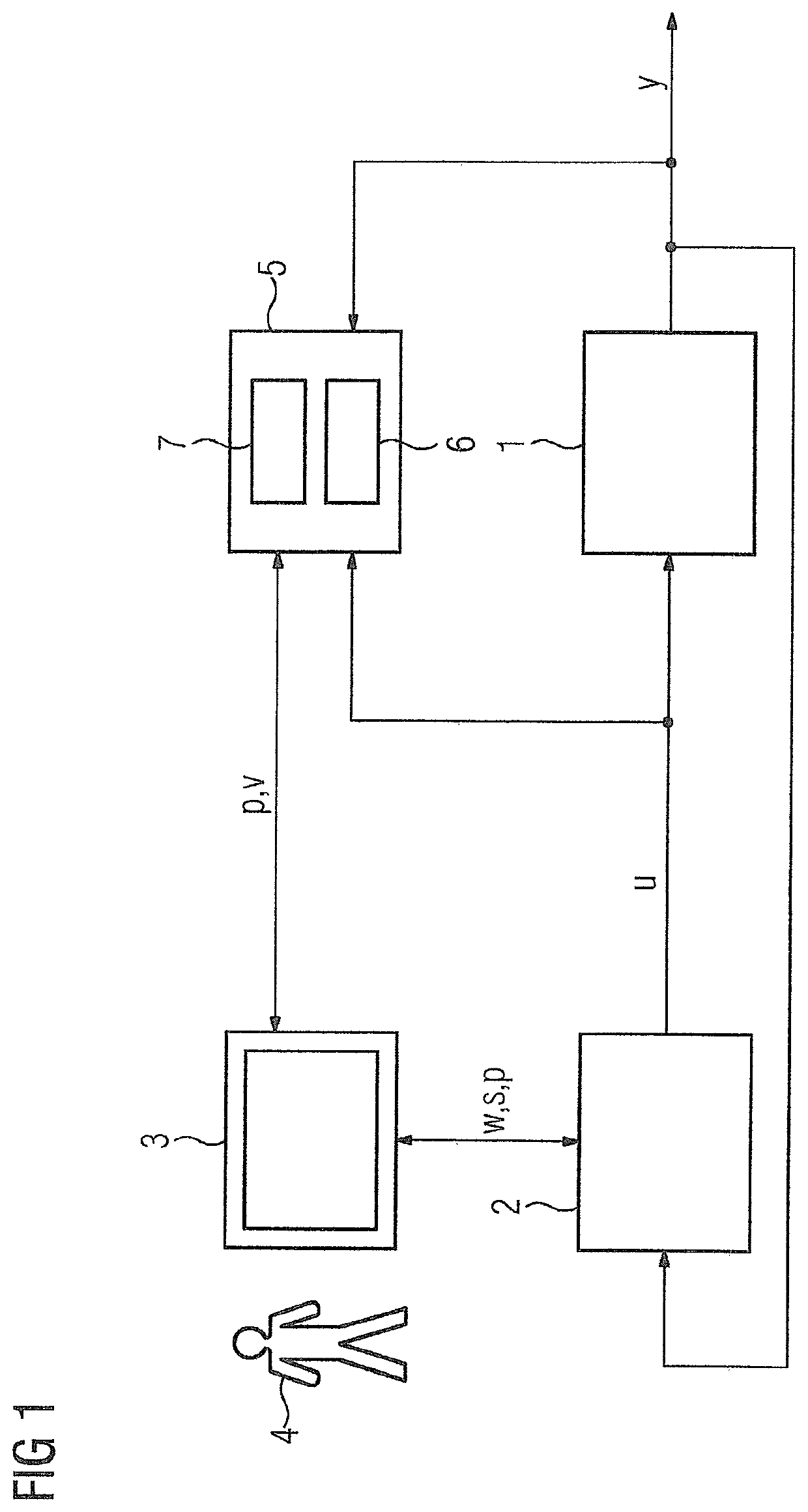
[0031]According to FIG. 1, a controlled system 1 with a controller 2 forms a part of an automated process engineering plant whose behavior is to be optimized. The controlled system 1 is, for example, a temperature control for a reactor that is filled with a process medium. The reactor is heated via a jacket that is connected to a separate water circuit for heating it. The water is heated by an electric continuous flow heater and pumped back into the jacket for heating the process medium. The process variable “temperature in the reactor” can be measured as a controlled variable y. Electric heating power supplied to the continuous flow heater is supplied as a manipulated variable u by the controller 2 for adjusting the temperature to a desired value w predefined by an operating unit 3. In addition, the control unit 3 can be used to select the structure of the controller 2 via a control signal s and to provide the defined controller type with the parameters p required in each case. Thi...


PUM


Abstract

A system and a method for determining the parameters of a controller for a controlled system, wherein a simulation model for the controlled system is identified based on detected input and output signals of the controlled system, where parameters of a master controller and a sequence controller used in a pilot control process for the controlled system are automatically defined based on model-based design methods for a controller designed as a model sequence controller, where the behaviour of the closed-loop system can be further improved via a subsequent optimization method, such that the controller can be advantageously designed without any particular control engineering expertise, and thus the frequency of use for model sequence controllers, with their many advantages, can be significantly increased in practical applications.

Description

CROSS-REFERENCE TO RELATED APPLICATIONS[0001]This is a U.S. national stage of application No. PCT / EP2017 / 079482 filed Nov. 16, 2017. Priority is claimed on EP Application No. 16199391 filed Nov. 17, 2016, the content of which is incorporated herein by reference in its entirety.BACKGROUND OF THE INVENTION1. Field of the Invention[0002]The invention relates to a system and to a method for determining the parameters of a controller for a controlled system, where the system is configured to determine a simulation model for the controlled system and to identify its parameters based on detected input and output signals of the controlled system, and where parameters of the controller for a desired behavior of the control loop are defined based on a model-based design method and the previously determined simulation model.2. Description of the Related Art[0003]In the assessment and design of a control loop, a distinction is made between the command behavior and the disturbance behavior. The ...

Claims


Application Information

Patent Timeline
Patent Type & Authority Applications(United States)
IPC IPC(8): G05B13/04G05B6/02
CPCG05B13/042G05B6/02G05B2219/42162
Inventor LABISCH, DANIEL
Owner SIEMENS AG
Why Eureka
Try Eureka