Control device and control method for power generation system

Active Publication Date: 2020-02-27
MITSUBISHI HEAVY IND ENGINE & TURBOCHARGER LTD
View PDF0 Cites 0 Cited by
  • Summary
  • Abstract
  • Description
  • Claims
  • Application Information

AI Technical Summary

Benefits of technology

[0009]According to the control device and the control method of a power generation system, the target voltage of the generator is reduced in accordance with the decrease amount of the detection value of the rotation speed of the engine or the frequency of the generator, if the detection value falls below an allowable variation value, when the load is connected to the generator via the circuit breaker. Accordingly, it is possible to prevent generation of an excessive load in the engine for changing the output voltage of the generator to the target voltage, and protect the engine from an excessive load. Furthermore, it is possible to suppress reduction of the rotation speed of the engine to the minimum, and shorten the recovery time of the rotation speed of the gas engine.
[0010]Further, according to the control device and the control method of the power generation system, the decrease amount of the target voltage of the generator is limited so that the normal operation of the load remains possible. Specifically, the target voltage of the generator is maintained at the allowable lower limit voltage determined on the basis of the output voltage that is allowable to carry out normal operation of the load or a value determined on the basis of the allowable lower limit voltage if the target voltage of the generator falls bel

Problems solved by technology

During shutdown of a grid power, when electric power generated by the generator of the power generation system is suppl

Method used


Image

  • Control device and control method for power generation system
  • Control device and control method for power generation system
  • Control device and control method for power generation system

Examples


Example

[0023]A preferable embodiment according to the above described control device of the power generation system will be described with reference to drawings.

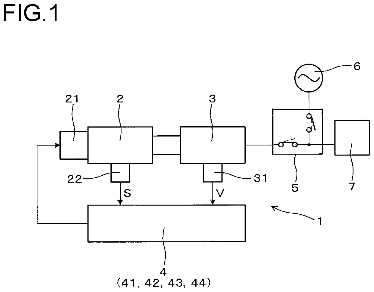
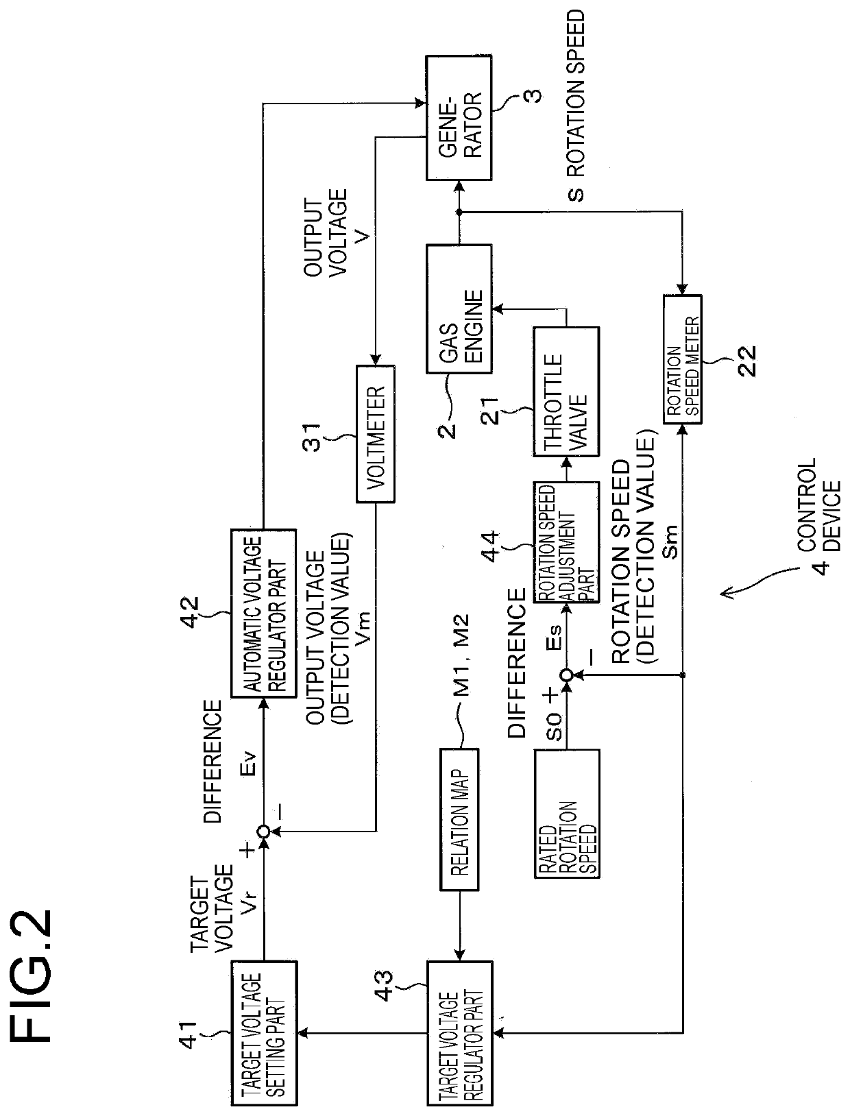
[0024]A control device 4 of a power generation system 1 according to the present embodiment is used for the power generation system 1 including a gas engine 2 and a generator 3, as depicted in FIG. 1. The power generation system 1 is configured to generate power with the generator 3 through combustion of the gas engine 2, and supply electric power to a load 7 via a circuit breaker 5 from the generator 3. As depicted in FIG. 2, the control device 4 includes an automatic voltage regulator part 42 configured to control the output voltage V of the generator 3 to the target voltage Vr of the generator 3, and a target voltage regulator part 43 configured to adjust the target voltage Vr of the generator 3.

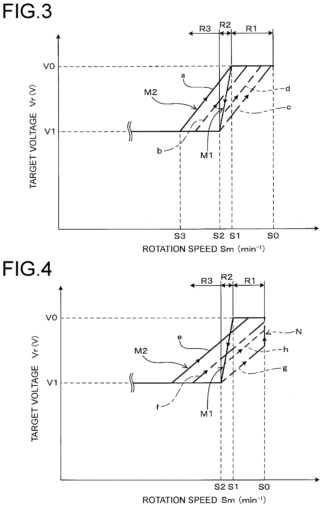
[0025]The target voltage regulator part 43 has a voltage decrease function, a voltage decrease limiting function, and a voltage increas...


PUM


Abstract

A control device 4 for a power generation system 1 includes a target voltage regulator part 43 configured to adjust the target voltage Vr of a generator 3. The target voltage regulator part 43 has: a voltage decrease function to reduce the target voltage Vr of the generator 3 in accordance with a decrease amount of a detection value Sm of a rotation speed S of a gas engine 2 or a frequency of the generator 3 if the detection value falls below an allowable variation value when a load is connected to the generator 3 via a circuit breaker 5; and a voltage decrease limiting function to maintain the target voltage Vr of the generator 3 at an allowable lower limit voltage determined on the basis of an output voltage V which is allowable to carry out normal operation of the load if the target voltage Vr of the generator 3 is lower than the allowable lower limit voltage.

Description

TECHNICAL FIELD[0001]The present invention relates to a control device and a control method for a power generation system.BACKGROUND ART[0002]A power generation system including a generator which generates power through combustion of an engine is used in, for instance, a co-generation system which enables recovery of cooling heat of the engine and waste heat of exhaust gas of the engine. Furthermore, a power generation system may be configured to be in connection with a grid power, so as to supply electric power to various loads powered by the grid power and supply electric power to essential loads during shutdown of the grid power.[0003]During shutdown of a grid power, when electric power generated by the generator of the power generation system is supplied to loads, rapid input of loads to the generator may lead to temporary reduction of the rotation speed of the engine. In this case, generation of an excessive load on the engine is avoided by reducing the target voltage of the ge...

Claims


Application Information

Patent Timeline
IPC IPC(8): H02P9/10
CPCH02P9/10H02P9/14Y02E20/14
Inventor TANIGUCHI, JUNICHIYAMAWAKI, HIROSHIITO, YOSHIHARUTAKATSUKA, MASAOKARATSU, TAKUYAABE, HAZUMUGOHARA, MAKOTO
Owner MITSUBISHI HEAVY IND ENGINE & TURBOCHARGER LTD
Why Eureka
Try Eureka