State estimation and localization for rov-based structural inspection

a technology applied in the field of state estimation and localization of rov-based structural inspection, can solve problems such as image noise or other difficulties in using in an automated context, and achieve the effect of increasing the belief state of the camera

Active Publication Date: 2020-02-27
CARNEGIE MELLON UNIV
View PDF0 Cites 1 Cited by
  • Summary
  • Abstract
  • Description
  • Claims
  • Application Information

AI Technical Summary

Benefits of technology

[0008]The present invention has several advantages over existing camera-based systems and methodologies due to its tightly coupled design between the camera hardware and the software algorithms. The ROV can be automatically tracked through visual serving to keep the robot in view, obviating the need for inspection personnel to manually control the external camera. Additionally, the system is capable of a self-initialization procedure, requiring minimal input from inspection personnel. This removes the need for technical domain experts to start the system. The system is also self-calibrating, using an initial known map of the geometry of the structure. The camera algorithms extract lines and points from the scene, inferring the position and orientation of the camera itself. Lastly, the invention has automated failure detection. The software will detect when ROV tracking is lost, or when the uncertainty in the estimated camera or ROV position and orientation becomes unreasonable. In these cases, the system automatically takes corrective action, such as suspending tracking and attempting to re-acquire the ROV. Additionally, camera maneuvers may be performed to increase the belief state of the camera.

Problems solved by technology

Underwater cameras exist for nuclear reactor inspection, but they are typically only used for human monitoring by inspection personnel.
Due to extreme radiation emitting from the walls, only the most hardened electronics are viable when in close proximity to the walls, and these electronics are typically prone to image noise or are otherwise difficult to utilize in an automated context.
However, operating in close proximity to the vessel walls is imperative for the robot to inspect the structure.

Method used


Image

  • State estimation and localization for rov-based structural inspection
  • State estimation and localization for rov-based structural inspection
  • State estimation and localization for rov-based structural inspection

Examples


Embodiment Construction

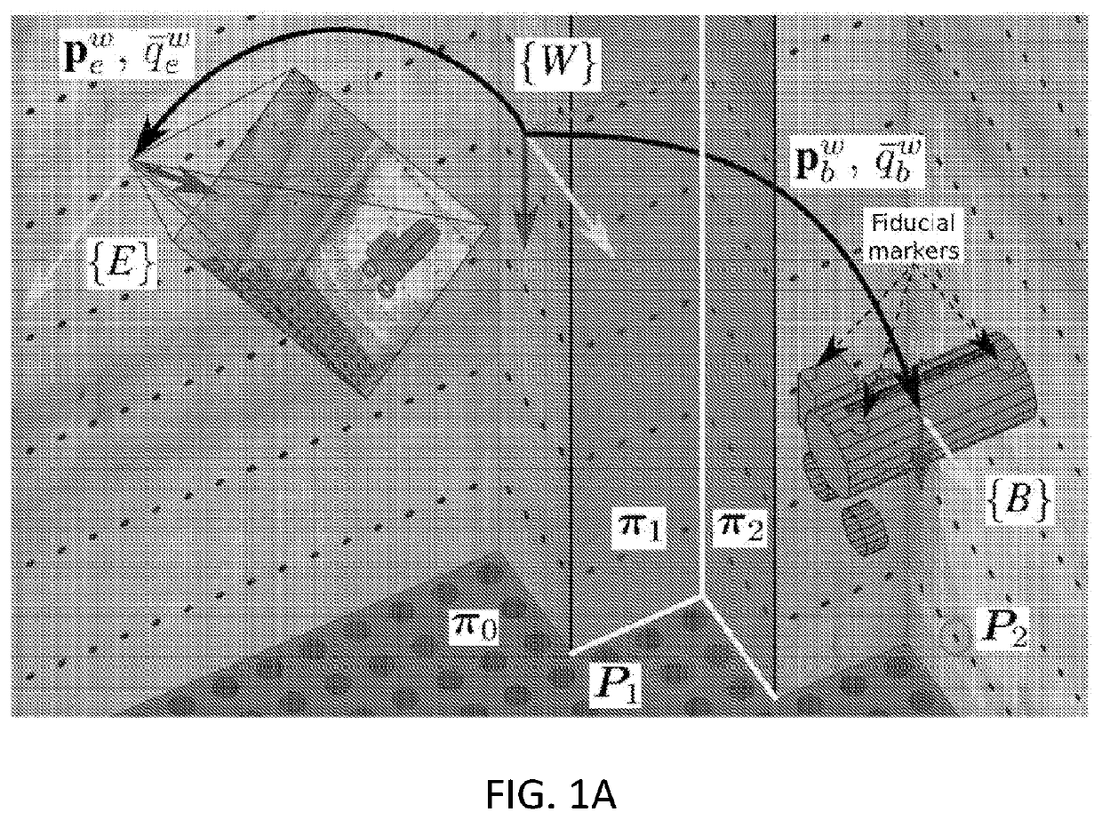
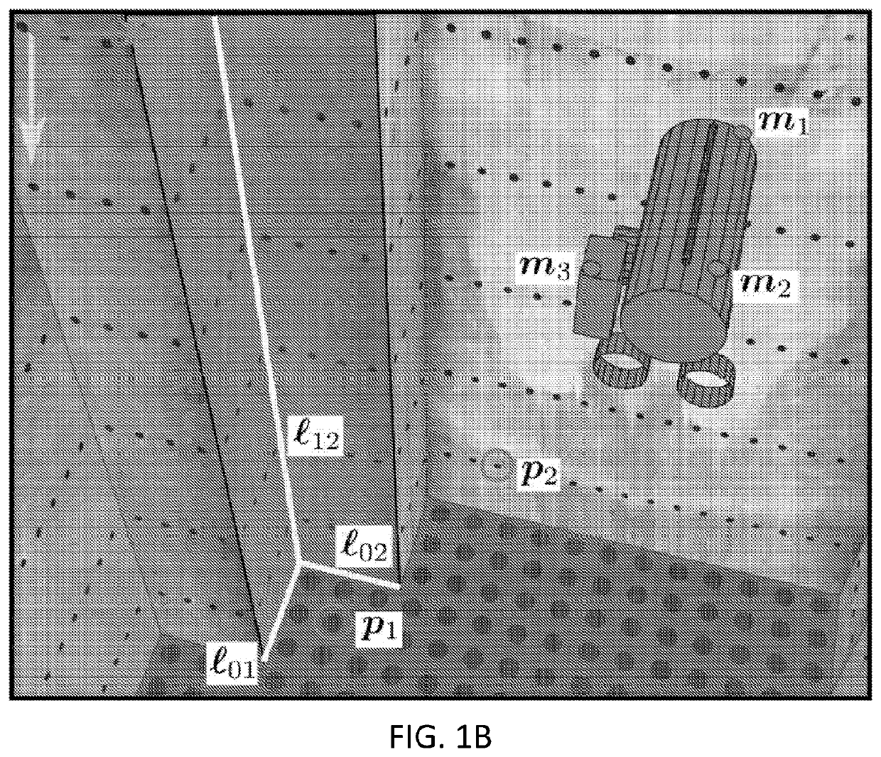
[0014]Note that, as used herein, the terms, “vehicle”, “remotely-operated vehicle”, “ROV” and “robot” are used interchangeably and refer to the vehicle being localized. Also, as used herein, the terms “pan-tilt-zoom”, “PTZ” and “camera” are used interchangeably, and refer to the external camera used for image capture for purposes of localization of the robot, and not a camera or cameras which may be mounted on the robot and used for capturing images of the structure being inspected.

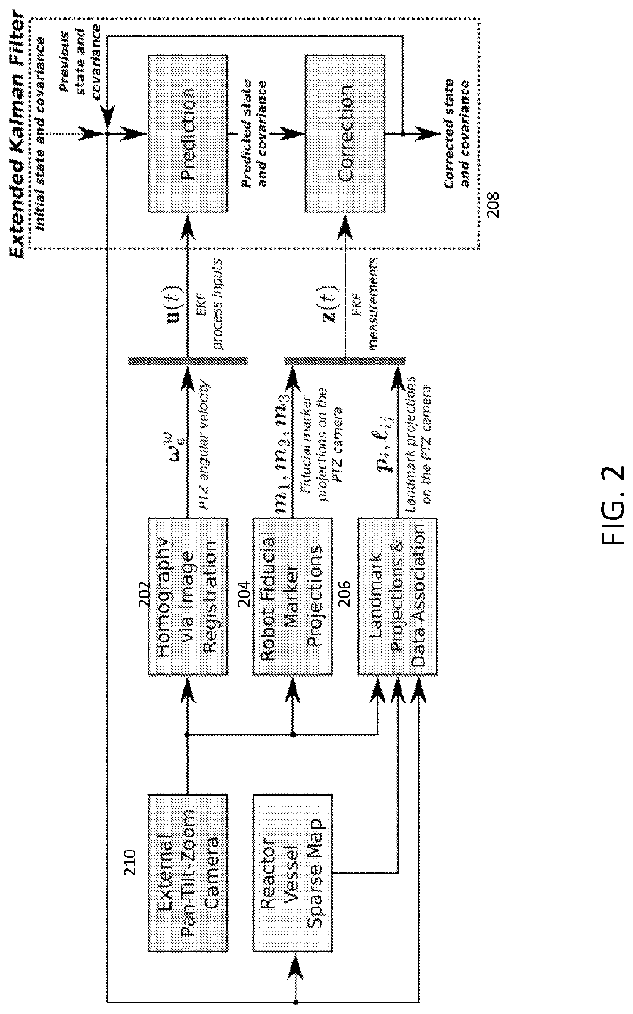
[0015]The invention uses a vision-based state estimation and localization framework to enable submersible robots to conduct precision inspection of nuclear reactor pressure vessels and other underwater structures. The framework is formulated as an extended Kalman filter (EKF) that is robust to sensor degradation and image corruption that may occur due to environmental effects, such as radiation and color attenuation. The proposed framework relies on a pan-tilt-zoom (PTZ) camera that is autonomously contro...


PUM


Abstract

A vision-based state estimation framework to estimate the state of an underwater remotely operated vehicle (ROV) used for inspection of an underwater structure, for example, a nuclear reactor pressure vessel. The framework employs an external overhead, pan-tilt-zoom (PTZ) camera as the primary sensing modality and incorporates prior knowledge of the geometry of the structure.

Description

RELATED APPLICATIONS[0001]This application claims the benefit of U.S. Provisional Patent Application Ser. No. 62 / 602,711, filed May 4, 2017.BACKGROUND OF THE INVENTION[0002]The use of vision for localizing underwater robots has been studied both in research experiments and in deployed field robots. Submersible robots, for example, remotely-operated vehicles (ROVs), typically utilize a range of sensor modalities, but the choice of sensor modalities may be restricted in environments with challenging conditions. As an example, walls of nuclear reactor containment vessels must be periodically inspected to ensure integrity. However, the existence of radiation in this environment may constrain the use of other sensors that could otherwise provide accurate localization, for example, inertial measurement units, gyroscopes, or depth sensors. Radiation-sensitive electronics can degrade and fail with exposure of a few kRad, which is often below the expected exposure dosage in this setting. The...

Claims


Application Information

Patent Timeline
Patent Type & Authority Applications(United States)
IPC IPC(8): H04N5/232G06T7/207G06T7/73B60R11/04G21C17/013G06V10/22G06V20/00
CPCG06T7/207G21C17/013B60R11/04H04N5/23229G06T7/74G21C17/01G21D3/001Y02E30/30Y02E30/00G06T7/277G06T7/246G01S5/16G01S5/163G06V20/00G06V20/10G06V10/22H04N23/80
Inventor MICHAEL, NATHANLEE, TIMOTHY E.BOIRUM, CURTIS
Owner CARNEGIE MELLON UNIV
Why Eureka
Try Eureka