
System and method for grid control of an electromagnetic ray tube

Active Publication Date: 2020-02-27
GENERAL ELECTRIC CO
View PDF0 Cites 2 Cited by
  • Summary
  • Abstract
  • Description
  • Claims
  • Application Information

AI Technical Summary

Benefits of technology

This patent is about a system and method for controlling the grid in an electromagnetic ray tube. The system includes a power source, rectifier, and grid conductor, which work together to convert AC current to DC current and power the grid electrode of the tube. The technical effect of this patent is to provide a more efficient and precise control over the electromagnetic ray tube's grid, which can improve performance and reliability.

Problems solved by technology

As will be appreciated, however, having the grid conductor with DC current and the filament conductor in the same high voltage cable generates a capacitance between the grid conductor and the filament conductor, which in turn, limits the speed at which tube current can be cycled on and off.

Method used


Image

  • System and method for grid control of an electromagnetic ray tube
  • System and method for grid control of an electromagnetic ray tube
  • System and method for grid control of an electromagnetic ray tube

Examples


Embodiment Construction

[0023]Reference will be made below in detail to exemplary embodiments of the invention, examples of which are illustrated in the accompanying drawings. Wherever possible, the same reference characters used throughout the drawings refer to the same or like parts, without duplicative description.

[0024]As used herein, the terms “substantially,”“generally,” and “about” indicate conditions within reasonably achievable manufacturing and assembly tolerances, relative to ideal desired conditions suitable for achieving the functional purpose of a component or assembly. As used herein, “electrically coupled,”“electrically connected,” and “electrical communication” mean that the referenced elements are directly or indirectly connected such that an electrical current may flow from one to the other. The connection may include a direct conductive connection, i.e., without an intervening capacitive, inductive or active element, an inductive connection, a capacitive connection, and / or any other sui...


PUM


Abstract

A system for grid control of an electromagnetic ray tube is provided. The system includes a power source, a rectifier, and a grid conductor. The power source is disposed apart from the electromagnetic ray tube and operative to generate an AC current. The rectifier is integrated into the electromagnetic ray tube and electrically coupled to a grid electrode of the electromagnetic ray tube. The grid conductor electrically couples the power source to the rectifier. The rectifier is operative to convert the AC current to a DC current that powers the grid electrode.

Description

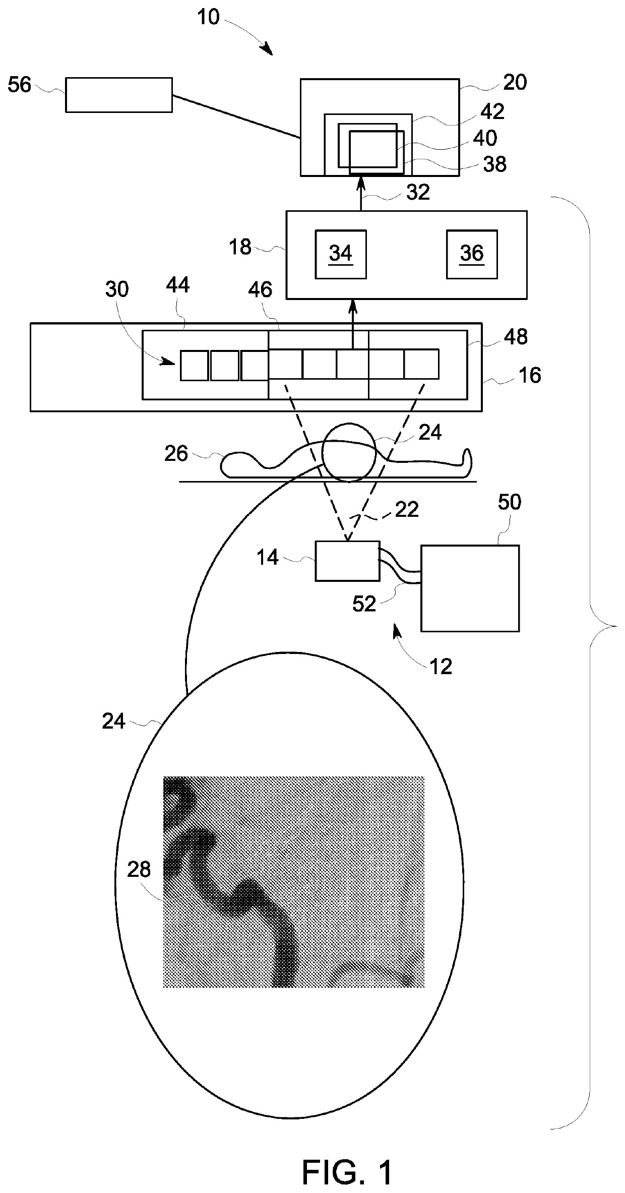
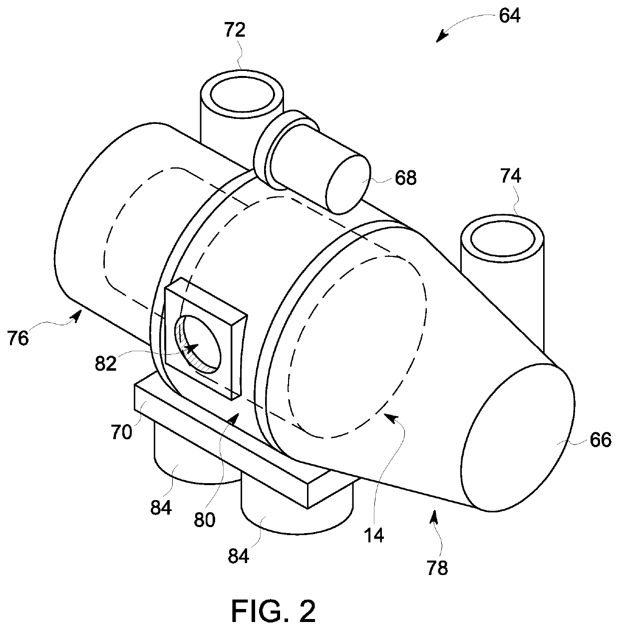
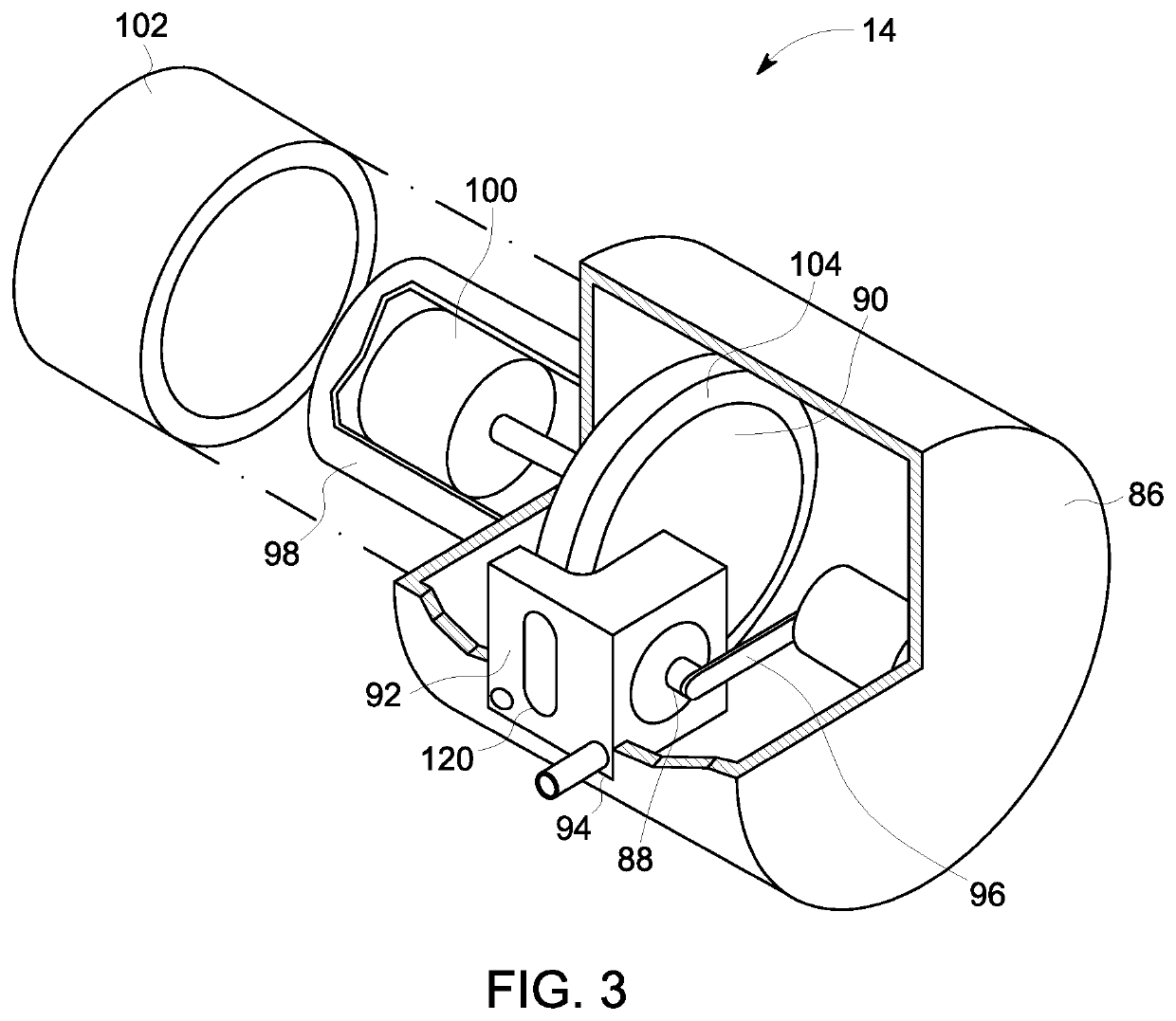
BACKGROUNDTechnical Field[0001]Embodiments of the invention relate generally to medical imaging systems, and more specifically, to a system and method for grid control of an electromagnetic ray tube.Discussion of Art[0002]Many imaging systems utilize X-ray tubes to generate images of an object. X-ray tubes generally include a cathode with electron emitter disposed at a distance from an anode within a vacuum vessel. The anode usually includes an impact zone that is generally fabricated from a refractory metal with a high atomic number, such as tungsten or tungsten alloy. A voltage difference is maintained between the cathode and the anode such that an electron beam, also referred to herein as the “tube current”, is generated by the electron emitter and strikes the anode within the impact zone, typically called the focal spot. As electrons within the electron beam impact the anode, their kinetic energy is converted to high-energy electromagnetic radiation, e.g., X-rays. Many such X-ra...

Claims


Application Information

Patent Timeline
IPC IPC(8): H05G1/08
CPCA61B6/504H05G1/085H05G1/06H05G1/20H05G1/32
Inventor ERNEST, PHILIPPEGAUTRAIS, STEPHANECLEMOT, ETIENNELEVILLY, NICOLASPOINCLOUX, DOMINIQUECAIAFA, ANTONIO
Owner GENERAL ELECTRIC CO
Features
  • Generate Ideas
  • Intellectual Property
  • Life Sciences
  • Materials
  • Tech Scout
  • Unparalleled Data Quality
  • Higher Quality Content
  • 60% Fewer Hallucinations
Learn More