Heat treatment apparatus

a heat treatment apparatus and heat treatment technology, applied in heat treatment apparatus, lighting and heating apparatus, furnaces, etc., can solve the problems of distortion, distortion, and workpiece distortion, and achieve efficient circulation and flow, less flow resistance, and efficient circulation

Active Publication Date: 2020-03-12
KOYO THERMO SYST CO LTD
View PDF0 Cites 1 Cited by
  • Summary
  • Abstract
  • Description
  • Claims
  • Application Information

AI Technical Summary

Benefits of technology

[0015]According to this configuration, the atmosphere inside the heat treatment chamber is heated by the pair of heaters disposed along the pair of side walls, and heat treatment by heating is applied to a workpiece disposed inside the heat treatment chamber. According to the configuration described above, when the centrifugal fan rotates between the pair of heaters disposed along the pair of side walls parallel to each other in the heat treatment chamber, air current that was sucked from the workpiece side and flowed outward in radial directions of the centrifugal fan further flows along the respective side walls and the respective heaters while flowing toward the respective side walls and the respective heaters due to an air blowing operation caused by rotation of the centrifugal fan and an air current flow direction regulating operation of the air current regulation unit. The air current that flowed along the respective side walls and the respective heaters passes through the workpiece and is sucked by the centrifugal fan, and flows outward in radial directions of the centrifugal fan again. Accordingly, during heat treatment by heating, the atmosphere inside the heat treatment chamber entirely efficiently circulates and flows so as to flow along the respective side walls and the respective heaters after passing through the workpiece, and pass through the workpiece again. Therefore, according to the configuration described above, generation of a flow deflected to a region with less flow resistance between the pair of heaters respectively disposed along the pair of side walls can be suppressed, and the atmosphere inside the heat treatment chamber can be entirely efficiently circulated during heat treatment by heating. According to the configuration described above, during heat treatment by heating, the atmosphere inside the heat treatment chamber can be entirely efficiently circulated, and in a state where variation in temperature distribution of the atmosphere inside the heat treatment chamber when rising in temperature is suppressed, the atmosphere inside the heat treatment chamber can be entirely more uniformly raised and changed in temperature. Accordingly, in each of the surface and the inside of the workpiece, variation in temperature change state among the respective portions of the workpiece when the respective portions rise in temperature during heat treatment is reduced, variation in stress state among the respective portions is reduced, and distortion due to the heat treatment during heating can be made smaller.
[0016](3) The heat treatment chamber may include a first side wall and a second side wall as the pair of side walls, the air current regulation unit may include a first air current restricting member and a second air current restricting member, the first air current restricting member may restrict a flow of the air current from the centrifugal fan to the first side wall side in a region which is at the first side wall side relative to the intermediate position inside the heat treatment chamber and in which outer circumferential edge portions of the rotary blade separate from the first side wall when the rotary blade rotates, and the second air current restricting member may restrict a flow of the air current from the centrifugal fan to the second side wall side in a region which is at the second side wall side relative to the intermediate position inside the heat treatment chamber and in which the outer circumferential edge portions of the rotary blade separate from the second side wall when the rotary blade rotates.
[0017]According to this configuration, the air current regulation unit consists of the first and second air current restricting members. A flow of the air current from the centrifugal fan to the first side wall side in the region in which the outer circumferential edge portions of the rotary blade of the centrifugal fan separate from the first side wall is restricted by the first air current restricting member. A flow of the air current from the centrifugal fan to the second side wall side in the region in which the outer circumferential edge portions of the rotary blade of the centrifugal fan separate from the second side wall is restricted by the second air current restricting member. Therefore, according to the configuration described above, the air current regulation unit can be realized by a simple structure provided with two members including the first and second air current restricting members.

Problems solved by technology

When applying heat treatment to a metallic workpiece, in each of the surface and the inside of the workpiece, if variation in temperature change state occurs among the respective portions of the workpiece during the heat treatment, variation in thermal stress state occurs among the respective portions, and distortion occurs in this workpiece.
As in the case of the heat treatment apparatus described in Patent Document 1, when applying heat treatment by heating to a workpiece, if variation in temperature change state occurs among the respective portions of the workpiece when rising in temperature during the heat treatment, distortion occurs in the workpiece.
When applying heat treatment by cooling to the workpiece by performing air cooling, if variation in temperature change state occurs among the respective portions of the workpiece when dropping in temperature during the heat treatment, distortion occurs in the workpiece.
However, much of the air current that was sucked from the workpiece side and flowed outward in radial directions of the centrifugal fan by the centrifugal fan flows in a direction with less flow resistance.
In this way, if a flow deflected to a region with less flow resistance is generated between the pair of side walls, it becomes difficult to entirely efficiently circulate the atmosphere inside the heat treatment chamber during heat treatment.
Therefore, variation in temperature distribution of the atmosphere inside the heat treatment chamber easily occurs, and it becomes difficult to entirely more uniformly change the temperature of the atmosphere inside the heat treatment chamber during heat treatment.
As a result, in each of the surface and the inside of the workpiece, variation in temperature change state occurs among the respective portions of the workpiece, variation in stress state occurs among the respective portions, and distortion easily occurs in the workpiece.

Method used


Image

  • Heat treatment apparatus
  • Heat treatment apparatus
  • Heat treatment apparatus

Examples


example

[0175][Example]

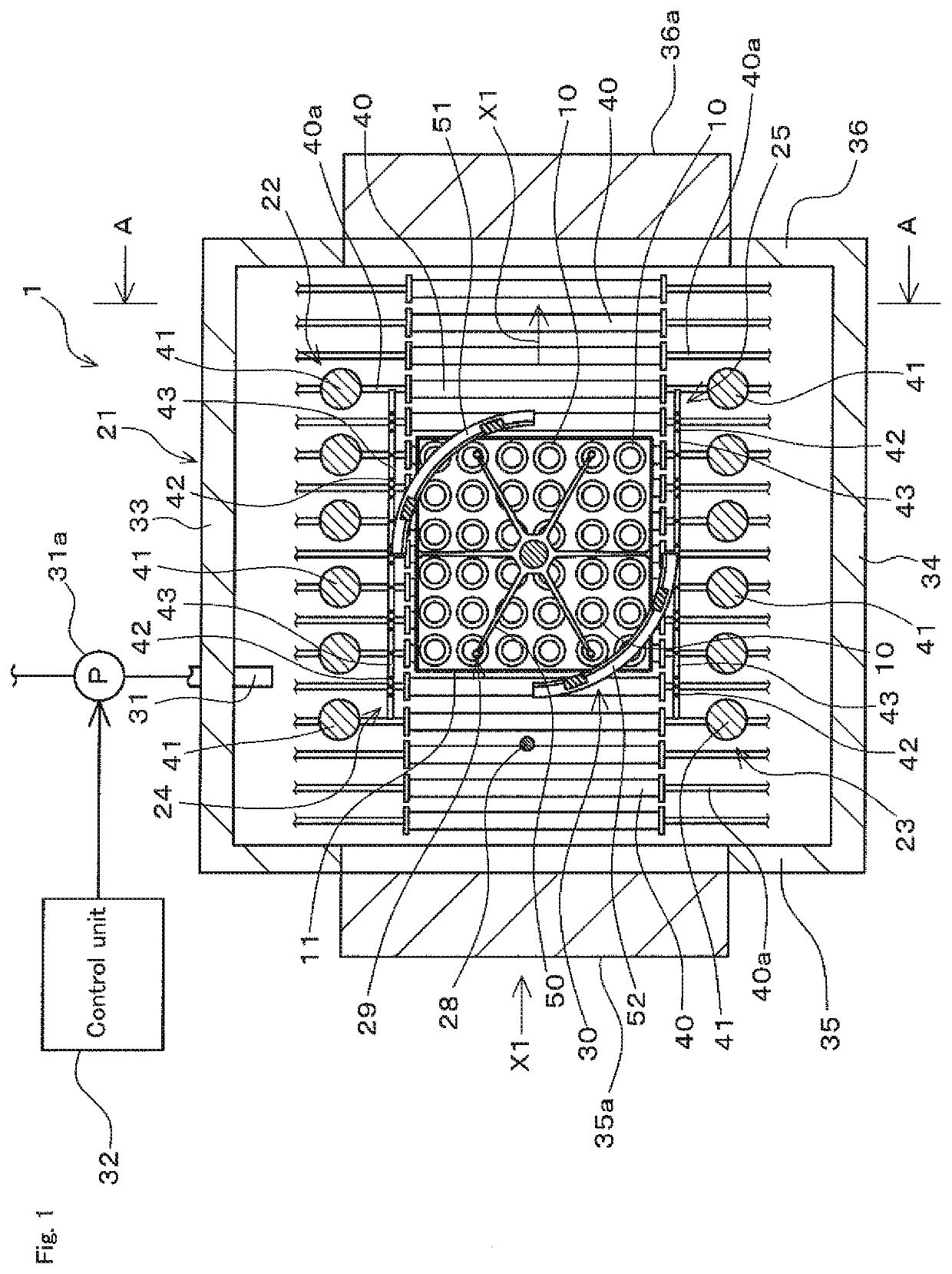
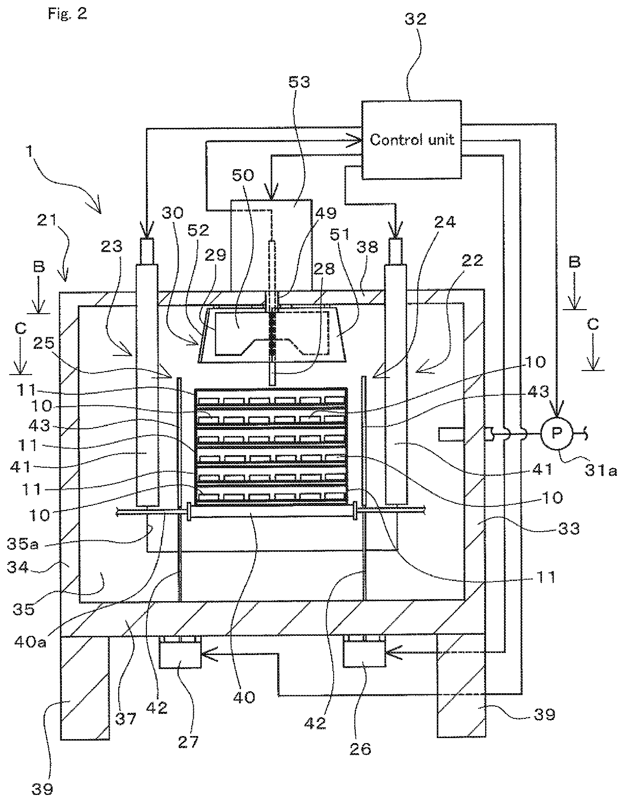
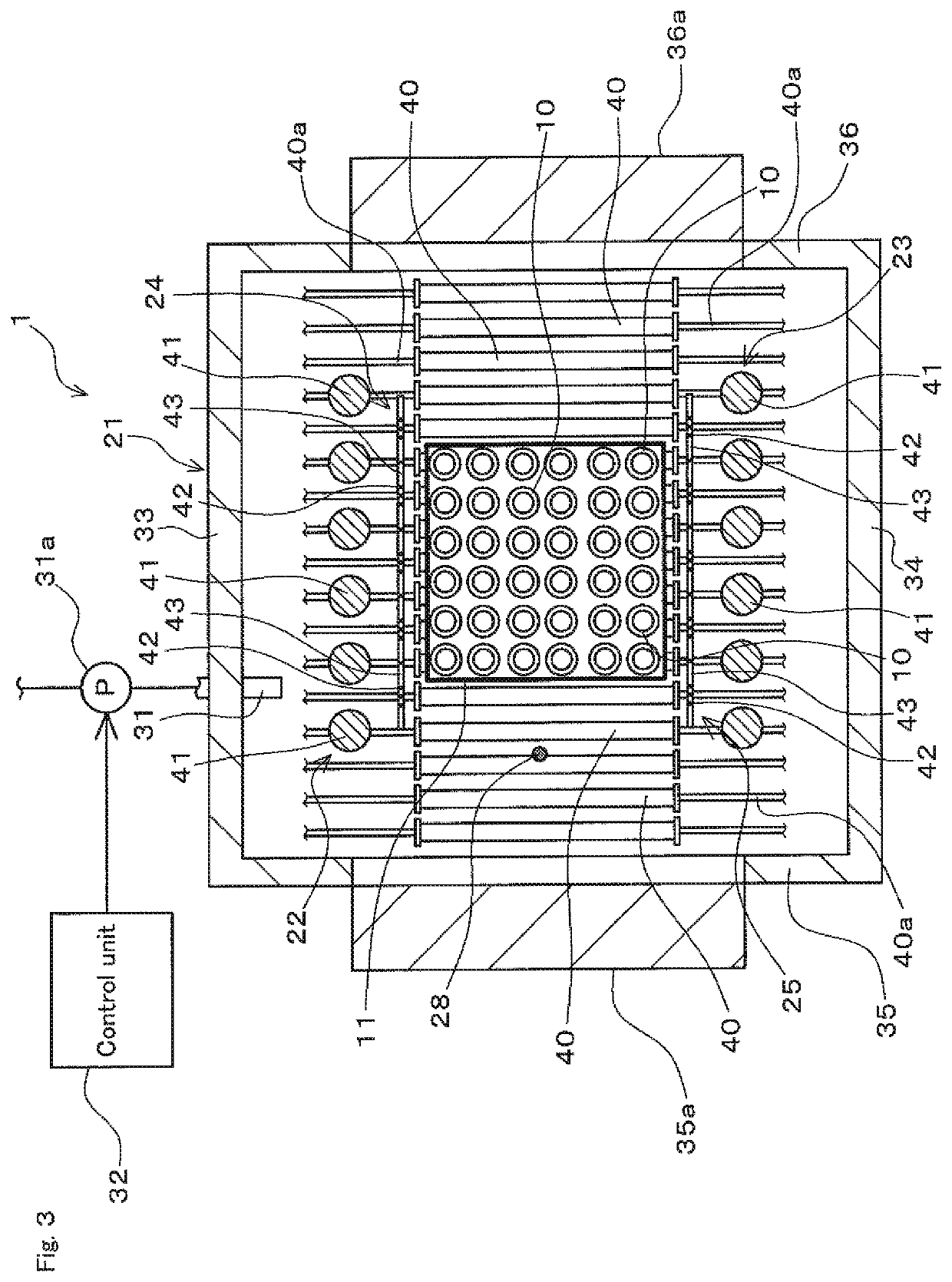
[0176]By using a heat treatment apparatus according to an example having the same configuration as that of the heat treatment apparatus 1 described in the embodiment described above, and a heat treatment apparatus according to a comparative example having the same configuration as a conventional configuration, heat treatment by heating was applied to ring-shaped metallic workpieces 10, and temperature changes of the workpieces 10 during the heat treatment were measured. The heat treatment apparatus according to the comparative example is configured as a heat treatment apparatus not including the shielding members (24, 25), the switching drive units (26, 27), and the air current regulation unit 30 in the heat treatment apparatus 1.

[0177]In the heat treatment using the heat treatment apparatus according to the example, the heat treatment was applied to the workpieces 10 by maintaining the shielding members (24, 25) in the shielding state continuously from the start of h...

third embodiment

[0191]The heat treatment apparatus 1 of the embodiment described above is configured so that the temperature measuring unit 28 measures a temperature at a predetermined temperature measurement position inside the heat treatment chamber 21 to measure the atmosphere inside the heat treatment chamber 21. On the other hand, the heat treatment apparatus 103 is configured to include a temperature measuring unit 60 that measures not a temperature of the atmosphere inside the heat treatment chamber 21 but a temperature of the workpiece 10.

[0192]The temperature measuring unit 60 is configured to include, for example, a radiation thermometer, and is provided as a temperature sensor to measure a temperature of one of the workpieces 10 disposed inside the heat treatment chamber 21. The temperature measuring unit 60 includes, for example, a thermometer storage case that extends downward in a tubular shape from the ceiling wall inside the heat treatment chamber 21 and stores the radiation thermo...


PUM

PropertyMeasurementUnit
temperatureaaaaaaaaaa

Abstract

Workpieces are disposed between a pair of side walls in a heat treatment chamber. A centrifugal fan is disposed to face the workpieces inside the heat treatment chamber, and sucks gas from the workpiece side and generates air current. In regions at the respective side wall sides relative to an intermediate position between the pair of side walls, an air current regulation unit regulates the air current so as to restrict flows of the air current from the centrifugal fan to the respective side wall sides when a rotary blade of the centrifugal fan rotates in regions in which outer circumferential edge portions of the rotating rotary blade separate from the respective side walls, and allows the flows in regions in which the outer circumferential edge portions of the rotating rotary blade approach the respective side walls.

Description

CROSS-REFERENCE TO RELATED APPLICATION[0001]This application claims priority to Japanese Patent Application No. 2018-168898. The entire disclosure of Japanese Patent Application No. 2018-168898 is hereby incorporated herein by reference.TECHNICAL FIELD[0002]The present invention relates to a heat treatment apparatus to apply heat treatment to metallic workpieces.BACKGROUND ART[0003]Conventionally, a heat treatment apparatus to apply heat treatment to metallic workpieces is known (for example, refer to Patent Document 1). The heat treatment apparatus described in Patent Document 1 includes a heat treatment chamber in which workpieces are disposed, and heaters and a centrifugal fan disposed inside the heat treatment chamber. The heat treatment chamber has a pair of side walls disposed parallel to each other, and the heaters are respectively disposed along the pair of side walls. The centrifugal fan is disposed to face workpieces inside the heat treatment chamber.[0004]The heat treatme...

Claims


Application Information

Patent Timeline
Patent Type & Authority Applications(United States)
IPC IPC(8): C21D9/00F27B9/10F27B9/30
CPCF27B9/10F27B9/3005C21D9/0006C23C8/20C21D1/767C21D1/34C21D9/40C21D9/32C21D1/06
Inventor NAKAMURA, TAKAHIROTETSUBAYASHI, HIROAKIUEDA, TAKESHI
Owner KOYO THERMO SYST CO LTD
Why Eureka
Try Eureka