
Integration of 3rd party geometry for visualization of large data sets system and method

a technology of data sets and integration methods, applied in the field of data analytics and engineering, can solve the problems of not having the tools and support of 3d rendering software to render large engineering 3d models, and not having a way to effectively establish a communication between 3d and 3d, so as to eliminate any limitation on size and performance, the effect of streamlined integration

Active Publication Date: 2020-03-12
AVEVA SOFTWARE LLC
View PDF0 Cites 1 Cited by
  • Summary
  • Abstract
  • Description
  • Claims
  • Application Information

AI Technical Summary

Benefits of technology

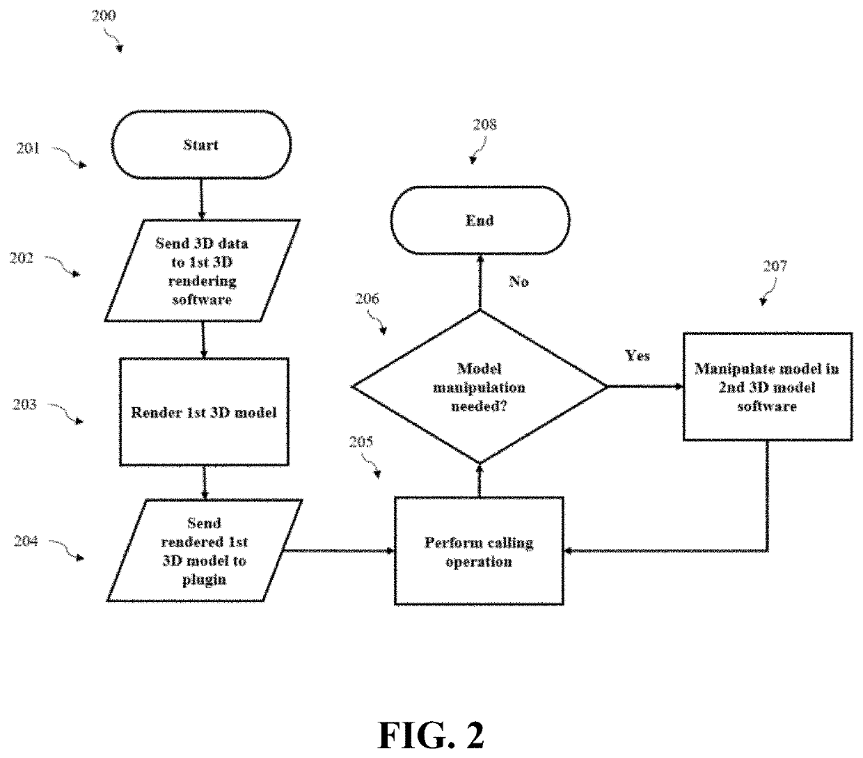
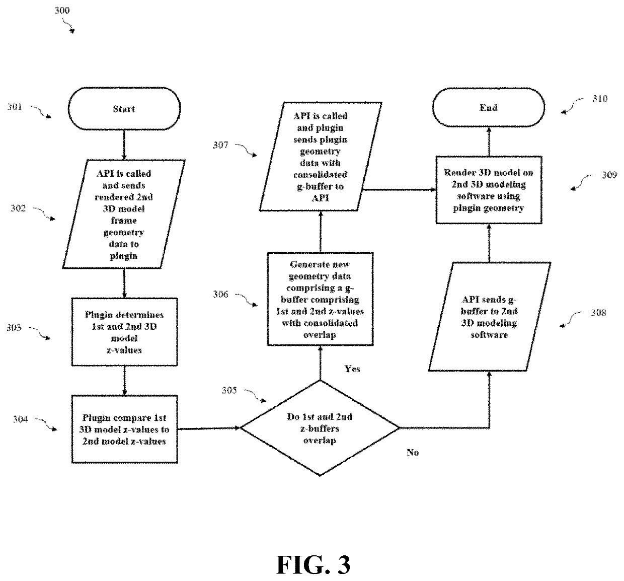
The patent describes a method for manipulating 3D renderings using computer interfaces. The method uses a g-buffer to create a combined rendering of first and second 3D model data where overlapping geometry is eliminated, allowing for interactive frame rates during manipulation. Additionally, the method includes a method for making calls to an application program from within the 3D rendering software to render the 3D model using a separate rendering software. This results in a "g-buffer" consisting of color, normal, depth and unique ID of the logical geometry primitive that contributed to the pixel at each screen position. The method reduces latency and provides faster manipulation of 3D renderings.

Problems solved by technology

In the case of large engineering 3D models, the 3D rendering software may not support or contain the tools necessary to render the large engineering 3D models.
However, because the 3D rendering software application does not support the functionality and rendering the separate 3D rendering platform provides, the 3D rendering software application must connect to and import the 3D model data from the separate 3D rendering platform.
In the current state of the art, there is no way to effectively establish a communication between a 3D rendering software application and a separate 3D rendering platform such that large engineering 3D model geometry can be imported and manipulated at an acceptable interactive rate.

Method used


Image

  • Integration of 3rd party geometry for visualization of large data sets system and method
  • Integration of 3rd party geometry for visualization of large data sets system and method
  • Integration of 3rd party geometry for visualization of large data sets system and method

Examples


Embodiment Construction

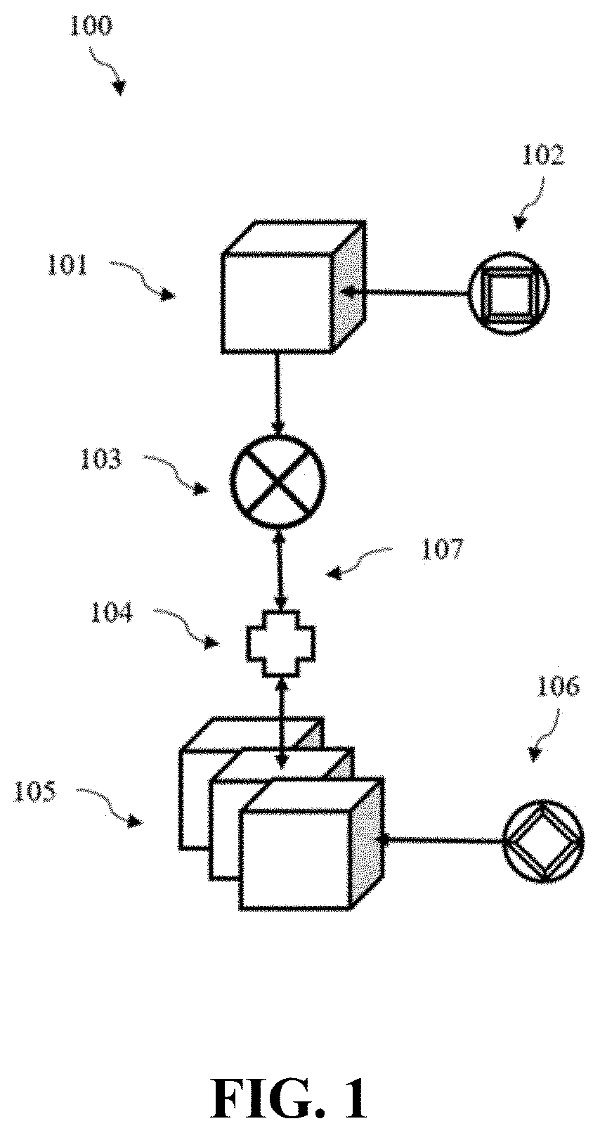
[0036]FIG. 1 depicts a portion of the system architecture 100 according to some embodiments. In some embodiments, the system comprises first 3D rendering software 101. According to some embodiments, first 3D model data 102 is in communication with and / or stored on first rendering software 101. In some embodiments, first rendering software 101 is in communication with a plugin 103.

[0037]In some embodiments, the plugin 103 is part of the first 3D rendering software 101. In some embodiments, plugin 103 is part of second 3D rendering software 105. In some embodiments, plugin 103 is part of a third 3D software, such as a cloud based software, for example. In some embodiments, any or all software that comprise part of the system 100 are cloud based software.

[0038]According to various embodiments, the system 100 comprises an API 104. In some embodiments, API 104 facilitates connection between the plugin 103 and the second 3D rendering software 105. In some embodiments, API 104 is part of t...


PUM


Abstract

A system provides the ability to import large engineering 3D models from a primary 3D rendering software into a secondary 3D rendering software that does not have the tools of the resources to render the larger 3D model on its own. The system uses a plugin to combine 3D data from the two software sources, and then return the combined 3D data to the secondary 3D rendering software. Components of the system can be remote or cloud based, and the system facilitates video streaming of 3D rendered models that can be manipulated on any computer capable of supporting a video stream.

Description

RELATED APPLICATIONS[0001]This application claims the benefit of and priority to U.S. Provisional Patent Application No. 62 / 729,371, filed Sep. 10, 2018, entitled “INTEGRATION OF 3RD PARTY GEOMETRY FOR VISUALIZATION OF LARGE DATA SETS SYSTEM AND METHOD”, the entire contents of which are incorporated herein by reference.BACKGROUND[0002]As the fields of data analytics and engineering expand, mathematical models of concepts are now commonly transformed into three dimensional (3D) visual representations using computers: the virtual 3D models can be manipulated as if they were real world 3D objects. The benefits for such a transformation are numerous, and include, for example, the ability to virtually perform operations such as fitting objects together, testing interface connections, running simulations, determining finite stress points, and storing iterations of designs.[0003]Often, it is necessary for multiple models from different file sources to be incorporated into a single renderin...

Claims


Application Information

Patent Timeline
Patent Type & Authority Applications(United States)
IPC IPC(8): G06T15/00G06F9/54G06T15/40
CPCG06T15/405G06T15/005G06F9/54G06T19/20G06T2219/2004G06T2219/2021
Inventor STEVENSON, DAVID MATTHEWLAURENDINE, CHASEBURTON, PAUL ANTONY
Owner AVEVA SOFTWARE LLC
Learn More