Vapor deposition source and vapor deposition apparatus, and method for manufacturing vapor deposition film

Inactive Publication Date: 2020-03-19
SHARP KK
View PDF0 Cites 3 Cited by
  • Summary
  • Abstract
  • Description
  • Claims
  • Application Information

AI Technical Summary

Benefits of technology

This patent is related to a vapor deposition source, apparatus, and method for making vapor deposition films. The technical effect of this invention is that it can reduce shadows and improve the overall uniformity of film thickness distribution.

Problems solved by technology

However, the vapor deposition particles incident on the mask opening at a shallow angle in an oblique direction cannot reach the film formed substrate through the mask opening.

Method used


Image

  • Vapor deposition source and vapor deposition apparatus, and method for manufacturing vapor deposition film
  • Vapor deposition source and vapor deposition apparatus, and method for manufacturing vapor deposition film
  • Vapor deposition source and vapor deposition apparatus, and method for manufacturing vapor deposition film

Examples


first embodiment

[0025]An embodiment of the disclosure will be described below with reference to FIGS. 1 to 5.

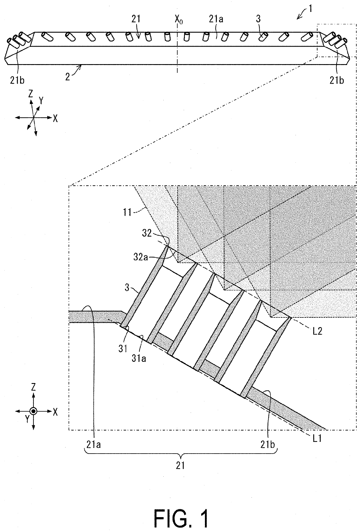
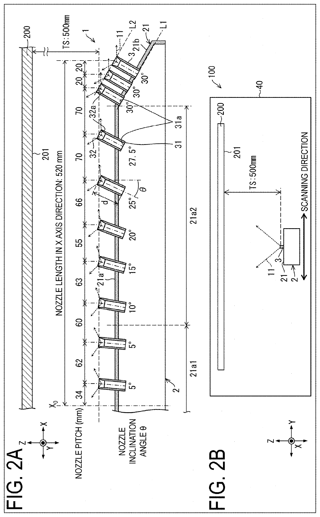
[0026]FIG. 1 is a perspective view illustrating in a partially enlarged manner, an outline configuration of a vapor deposition source 1 according to the first embodiment in conjunction with spread of vapor deposition particles ejected from the vapor deposition source 1. FIG. 2A is a cross-sectional view illustrating an outline configuration of a main portion of the vapor deposition source 1 according to the first embodiment in conjunction with an example of dimensions of the main portion and a film formed substrate 200, and FIG. 2B is a cross-sectional view illustrating an outline configuration of a main portion of a vapor deposition apparatus 100 including the vapor deposition source 1 according to the first embodiment.

[0027]Hereinafter, description will be given, assuming that a horizontal axis direction being an arrangement direction of nozzles 3 in the vapor deposition source 1 and exten...

first modified example

[0067]Note that in the first embodiment, the case where the nozzles 3 are provided in a row in a line form (that is, on an identical axis) on the upper face 21 of the containing unit 2 is describe as an example. However, the first embodiment is not limited to this case. The nozzles 3 may be provided in multiple rows in a line form.

second modified example

[0068]In addition, in the first embodiment, the case where the vapor deposition film serves as, for example, a function film in an organic EL element (Organic Light-Emitting Diode: OLED) is describe as an example. However, the first embodiment is not limited to this case. The vapor deposition film may serve as, for example, a function film in an inorganic light-emitting diode element (inorganic EL element) or a Quantum-dot Light Emitting Diode (QLED) element. The vapor deposition source 1 may be used generally for film formation (manufacturing) of a vapor deposition film.

[0069]The vapor deposition source 1 and the vapor deposition apparatus 100 can be used suitably, for example, as a manufacturing apparatus of an EL display device such as an organic EL display device including an Organic Light-Emitting Diode (OLED) element, and an inorganic EL display device including an inorganic light-emitting diode element, and a QLED display device including a QLED element.


PUM

PropertyMeasurementUnit
Temperatureaaaaaaaaaa
Fractionaaaaaaaaaa

Abstract

The vapor deposition source includes a containing unit configured to contain vapor deposition particles and a plurality of nozzles aligned in a line form along an X axis direction, and in the vapor deposition source, the plurality of nozzles at an end portion in the X axis direction of the containing unit protrude in an oblique direction toward the end portion in the X axis direction, arrangement density of nozzles provided at the end portion in the X axis direction of the containing unit is higher than arrangement density of nozzles provided at a center portion of the containing unit, and a line connecting upper end faces of the nozzles adjacent to each other at the end portion in the X axis direction of the containing unit is linearly provided.

Description

TECHNICAL FIELD[0001]The disclosure relates to a vapor deposition source referred to as a line source or a linear source and a vapor deposition apparatus including the vapor deposition source, and a method for manufacturing a vapor deposition film by using a vapor deposition particle ejecting device.BACKGROUND ART[0002]In a flat panel display such as an electroluminescence (EL) display device including a light emitting element, a vacuum vapor deposition technique is commonly used to form a function layer such as a light-emitting layer to be provided between a pair of electrodes and to constitute the light emitting element.[0003]In manufacturing such a display device, in view of display screen enlargement, manufacturing cost saving, and the like, a large-sized mother substrate being a large-area substrate is used in many cases as a film formed substrate. In the case of performing film formation of a vapor deposition film onto such a large-sized film formed substrate, scan vapor depos...

Claims


Application Information

Patent Timeline
IPC IPC(8): C23C14/24H01L51/00H01L51/56H01L33/00
CPCH01L51/56H01L33/005C23C14/243H01L51/0011H01L51/001H05B33/10C23C14/24C23C14/12C23C16/45578H10K71/164H10K71/00H10K71/16H10K71/166
Inventor NISHIGUCHI, MASAO
Owner SHARP KK
Why Eureka
Try Eureka