Multi-Cycle Wellbore Clean-Out Tool
a multi-cycle, wellbore technology, applied in the direction of wellbore/well accessories, earthwork drilling and mining, flushing, etc., can solve the problems that the bha cannot take advantage of gravity to bring the filling material, and the use of reverse flow clean-out valves is often impractical in connection with horizontal wellbores, so as to reduce the distance between the radial slots of the plunger and the sea
- Summary
- Abstract
- Description
- Claims
- Application Information
AI Technical Summary
Benefits of technology
Problems solved by technology
Method used
Image
Examples
second embodiment
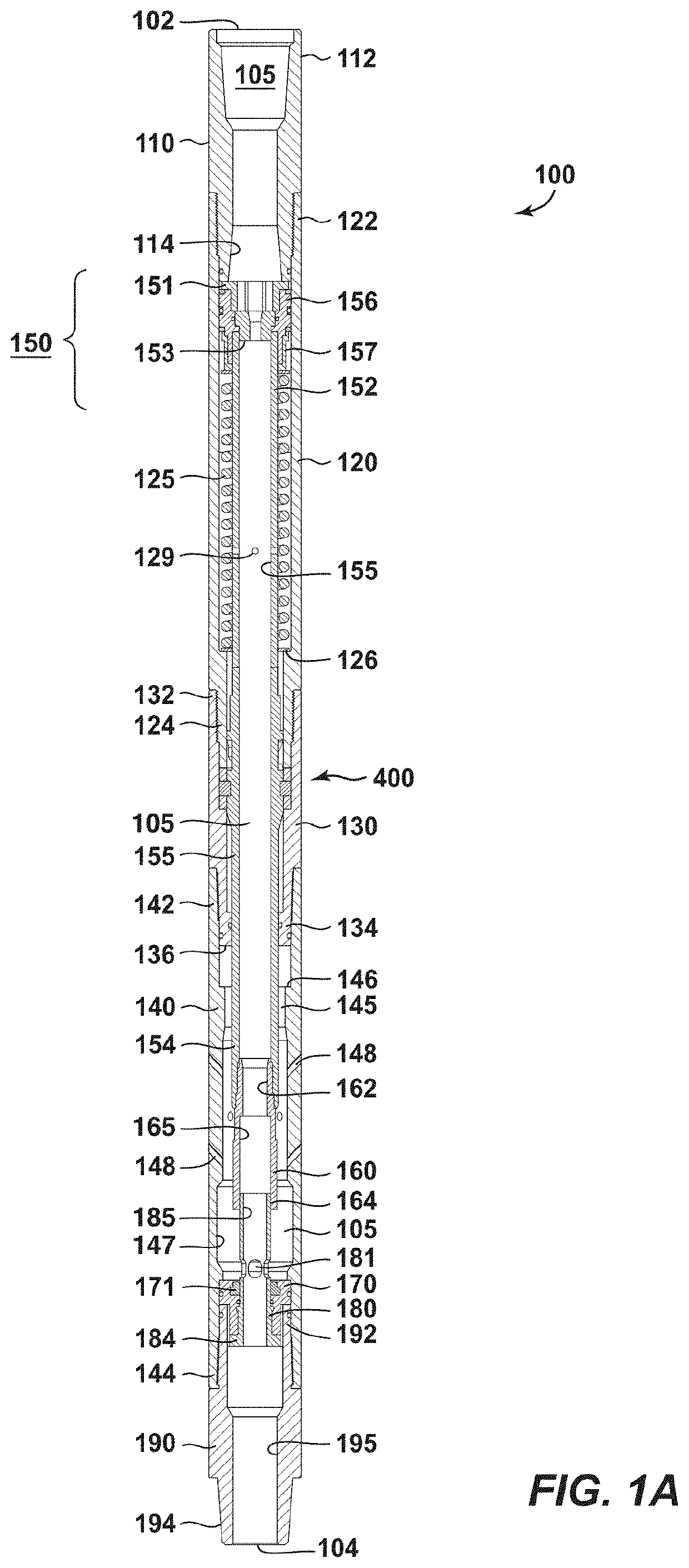
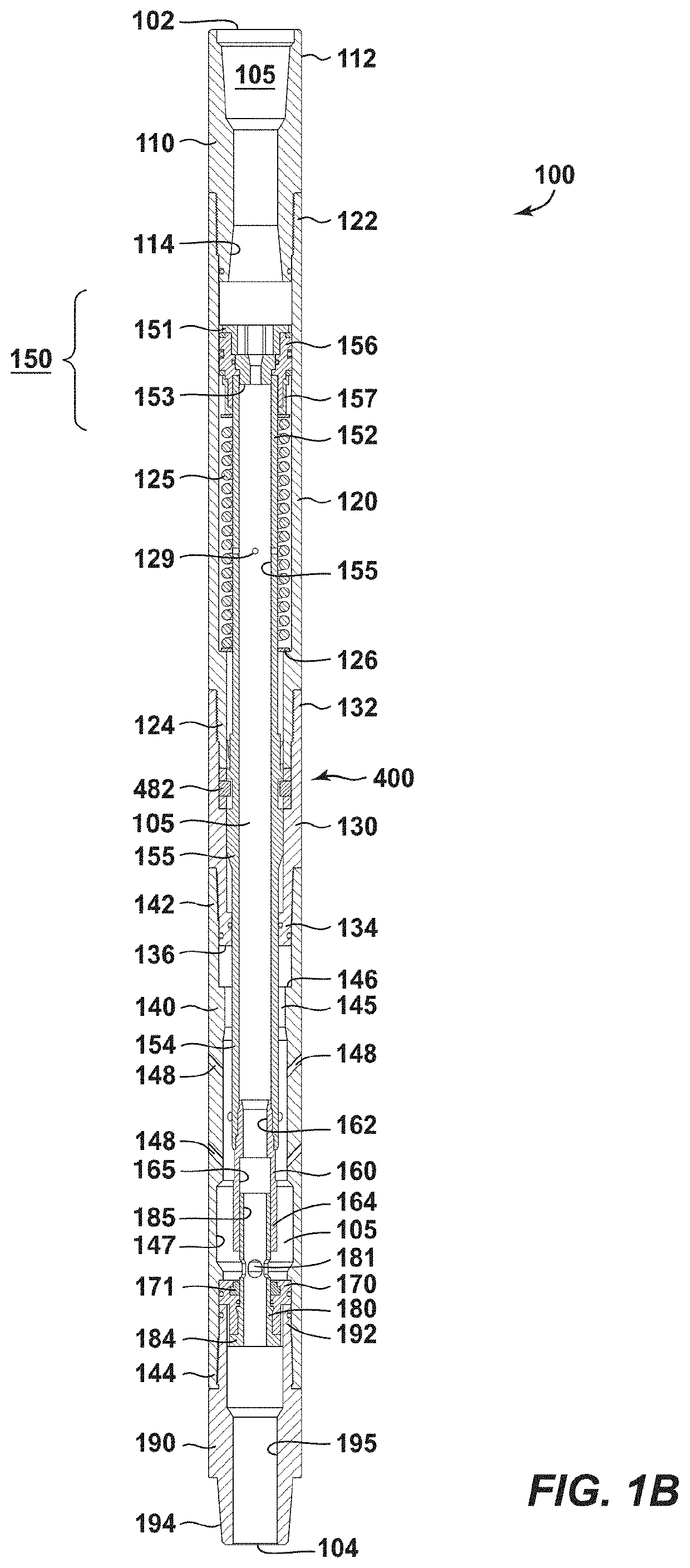
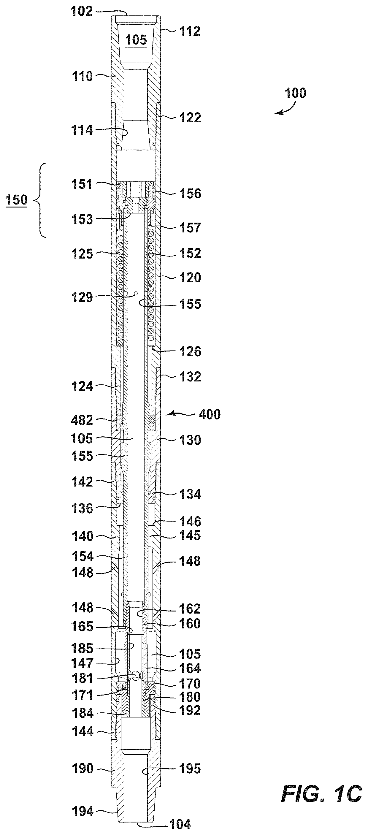
[0141]FIG. 2A is a cross-sectional view of a clean-out tool 200 of the present invention, in a In this view, the clean-out tool 200 is again in its run-in position wherein a substantial portion of injected fluid flows to the back jetting ports 148, while the remaining fluid flows through the lower sub 190 of the tool 200 en route to a next downhole tool. The clean-out tool 200 is built in accordance with the clean-out tool 100 described above. However, in this design a restricted orifice stem 280 has been placed below the plunger 160 in lieu of the stem 180. The restricted orifice stem 280 has a more restrictive through opening 285, limiting the amount of working fluid that can pass through the stem 280.
[0142]Beneficially, the stem 280 provides a better indicator at the surface as to the position of the plunger 160 (via pump pressure) during cycling. Also as noted, the use of the restricted-orifice stem 280 and its flow-through opening 285 directs a greater percentage of injected f...
embodiment 200
[0147]FIG. 3 is a perspective view of a positive displacement motor 300. This provides an example of a tool that may be connected to the lower sub 190. Preferably, the positive displacement motor 300 would be used in connection with the embodiment 200 of FIGS. 2A-2C. It is understood that the positive displacement motor 300 is merely illustrative; other positive pressure tools may be placed downstream of the seat 170.
[0148]It can be seen that the motor 300 includes an elongated tubular body 310. The body 310 defines a fluid in-take end 312 and a fluid outlet end 314. The positive displacement motor 300 operates with a rotor and a stator residing within the tubular body 310. In one aspect, the positive displacement motor 300 is used as an agitator, sending pressure pulses across the wellbore downhole while cleaning. In another aspect, a small drill bit (not shown) is connected to the outlet end 314, and is turned by the rotor of the motor 300. The drill bit may also be used for clean...
third embodiment
[0185]As an alternative to the clean-out tool 100 and its annular seal 171, a clean-out tool is presented herein In this embodiment, the annular seal 171 and the stem 180 are removed. This alternative clean-out tool is presented at 1200 in FIGS. 12A, 12B and 12C.
[0186]FIG. 12A is a cross-sectional view of the clean-out tool 1200, in the third embodiment. In this view, the clean-out tool (or “flow diverter”) 1200 is again in its run-in position wherein a significant portion of injected clean-out fluid flows to back jetting ports 148, while a remaining portion flows through the end of the tool 1200. Specifically, a portion of the clean-out fluids flow through the bore 195 of the lower sub 190.
[0187]The clean-out tool 1200 is built in accordance with the clean-out tool 100 described above. However, in FIG. 12A a new seat design 1270 is provided. Of importance, the stem 180 from FIG. 1A has been removed from the seat 1270. In addition, the slots 181 that previously resided within the st...
PUM
 Abstract
Description
Claims
Application Information
 - R&D
- Intellectual Property
- Life Sciences
- Materials
- Tech Scout
- Unparalleled Data Quality
- Higher Quality Content
- 60% Fewer Hallucinations
Browse by: Latest US Patents, China's latest patents, Technical Efficacy Thesaurus, Application Domain, Technology Topic, Popular Technical Reports.
© 2025 PatSnap. All rights reserved.Legal|Privacy policy|Modern Slavery Act Transparency Statement|Sitemap|About US| Contact US: help@patsnap.com


