Solid state lighting lamp

a lighting lamp and solid state technology, applied in the field of solid state lighting lamps, can solve the problems of increasing the weight of the lamp, increasing the cost, depressing the profit margin, etc., and achieve the effect of cost-effectiveness

Active Publication Date: 2020-03-19
SIGNIFY HLDG BV
View PDF0 Cites 4 Cited by
  • Summary
  • Abstract
  • Description
  • Claims
  • Application Information

AI Technical Summary

Benefits of technology

[0006]The present invention is based on the insight that by securing the heatsink modules to a separate body, the structural integrity of the lamp may be provided to a large extent by the separate body such that the heatsink modules may be made more lightweight, e.g. thinner, thereby reducing the overall weight of the solid state lighting lamp because the separate body may be made of a lightweight material such as a polymer material due to the fact that the separate body does not need to provide a significant contribution to the thermal dissipation capacity of the heatsink modules.
[0018]The solid state lighting lamp may further comprise a base including an electrical connector and a cap opposite said base, wherein the body and the heatsink modules extend between the base and the cap. Preferably, the cap comprises a plurality of air vents such that air can flow through the solid state lighting lamp to aid heat transfer between the heatsink modules and the air within the solid state lighting lamp such that the temperature of the solid state lighting elements can be better controlled.

Problems solved by technology

However, in order to obtain the required structural integrity of the closed body, each heat sink module is relatively thick, which increases weight of the lamp and adds to its cost.
This is problematic, as the market for SSL lamps is notoriously competitive, which depresses profit margins.
What is more, with demand for increasing luminous power to be produced by such lamps, the thermal requirements become more challenging, which leads to the weight of the lamp increasing due to larger (heavier) heat sinks, to such an extent that it becomes challenging to keep the weight of the lamp below its maximum allowed weight for health and safety considerations.

Method used


Image

  • Solid state lighting lamp
  • Solid state lighting lamp
  • Solid state lighting lamp

Examples


Embodiment Construction

[0030]It should be understood that the Figures are merely schematic and are not drawn to scale. It should also be understood that the same reference numerals are used throughout the Figures to indicate the same or similar parts.

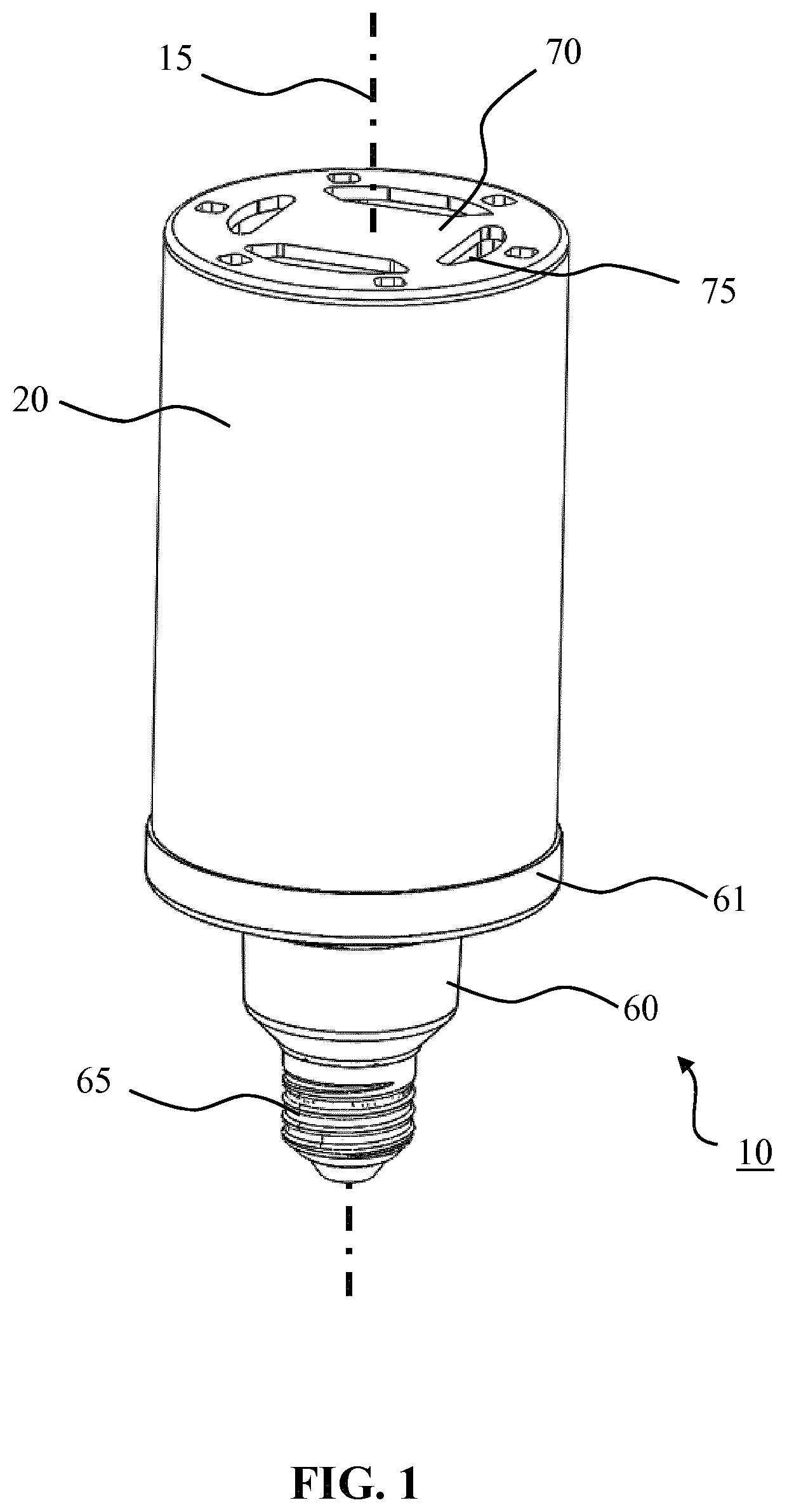
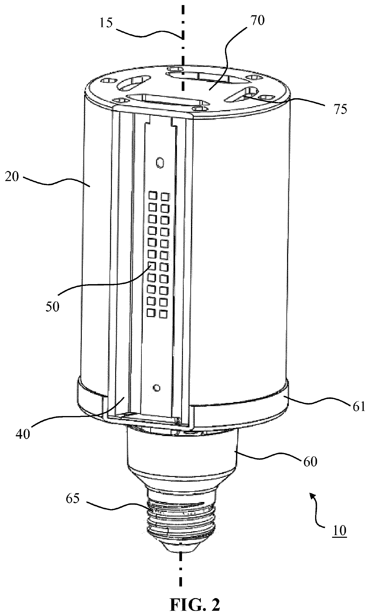
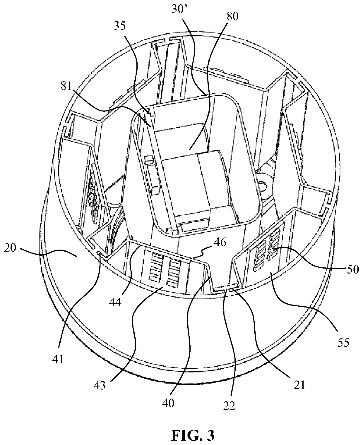
[0031]FIGS. 1 and 2 schematically depicts a perspective view and FIG. 3 schematically depicts a perspective cross-sectional view of a solid state lighting lamp 10 according to an embodiment of the present invention. The solid state lighting lamp 10 comprises an optical housing 20 extending between a base 60 and a cap 70. FIG. 2 presents the same view of the solid state lighting lamp 10 as FIG. 1, with the exception that in FIG. 2 an elongate portion of the optical housing 20 has been cut away to show the internals of the solid state lighting lamp 10. A central axis 15 of the solid state lighting lamp 10 extends between the base 60 and the cap 70. The base 60 typically comprises an electrical connector (fitting) for connecting the solid state lighting lamp to ...


PUM

PropertyMeasurementUnit
volumeaaaaaaaaaa
energy consumptionaaaaaaaaaa
weightaaaaaaaaaa

Abstract

A solid state lighting lamp (10) is disclosed comprising a plurality of heatsink modules (40) each extending in alignment with a central axis (15) of the lamp, each heatsink module carrying a plurality of solid state lighting elements (50); and a body (20) extending in alignment with said central axis and delimiting an inner volume of the lamp, wherein the heatsink modules are affixed to said body. The body is the optical housing, i.e. the light exit window of the lamp.

Description

FIELD OF THE INVENTION[0001]The present invention relates to a solid state lighting lamp comprising a plurality of heatsink modules each extending in alignment with a central axis of the lamp, each optical module carrying a plurality of solid state lighting elements.BACKGROUND OF THE INVENTION[0002]Modern society is witnessing a shift towards solid state lighting (SSL) applications such as LED applications. Such applications have improved longevity, e.g. through improved robustness against accidental impacts, and superior energy consumption characteristics compared to traditional light sources such as incandescent and halogen light sources. One such an application domain is outdoor lighting, where traditionally HPS and high-intensity discharge (HIS) lamps have been used to illuminate outdoor areas, e.g. public outdoor areas such as streets, squares, motorways and so on. Another type of lamp that is commonly replaced by SSL equivalents is a compact fluorescent lamp (CFL). Such SSL la...

Claims


Application Information

Patent Timeline
Patent Type & Authority Applications(United States)
IPC IPC(8): F21V29/71F21K9/232F21K9/237F21V29/83F21V17/10
CPCF21V29/71F21K9/237F21Y2115/10F21Y2107/50F21V29/83F21V3/04F21V17/104F21K9/232F21Y2103/10F21V17/10
Inventor DUAN, XIAOQINGPEI, ZHIGANGMO, LINGGEN
Owner SIGNIFY HLDG BV
Why Eureka
Try Eureka