System and methods for updating a reference time from a decaying rotational period of a pulsar

a technology of decaying rotational period and reference time, which is applied in the direction of x/gamma/cosmic radiation measurement, using reradiation, instruments, etc., can solve the problems of limited timekeeping methods and known clocks

Active Publication Date: 2020-03-19
BOOZ ALLEN HAMILTON INC
View PDF2 Cites 12 Cited by
  • Summary
  • Abstract
  • Description
  • Claims
  • Application Information

AI Technical Summary

Benefits of technology

[0003]An embodiment of a system for updating a reference time from a decaying rotational period of one or more pulsars can include: a database (DB) configured to store pulsar information about one or more pulsars, the pulsar information including: coordinates for the one or more pulsars; a recorded rate of rotation (RROR) for the one or more pulsars, recorded from observation at a previous reference time, wherein the RROR has a RROR period; a rotational rate of decay (RROD) function for the one or more pulsars; and a recorded reference time for the one or more pulsars, periodically updated by an internal clock; a sensor configured to collect electromagnetic pulsar radiation from the one or more pulsars and generate sensor data; a signal processor module configured to receive the sensor data, generate an observed rate of rotation (OROR) signal profile based on the sensor data and the RROR, generate a current rate of rotation (CROR) for the one or more pulsars from the OROR signal profile, and update the RROR from the CROR; and a time processor module configured to receive the RROD function and the CROR, and to solve the RROD function to output a reference time

Problems solved by technology

Known clocks and timekeeping methods are limited in that they rely on a previously configured clock that holds the reference time.
This can be problematic

Method used


Image

  • System and methods for updating a reference time from a decaying rotational period of a pulsar
  • System and methods for updating a reference time from a decaying rotational period of a pulsar
  • System and methods for updating a reference time from a decaying rotational period of a pulsar

Examples


Embodiment Construction

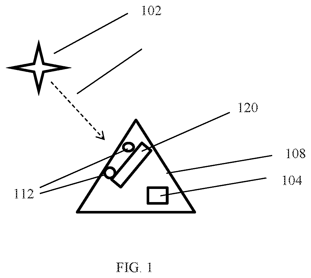
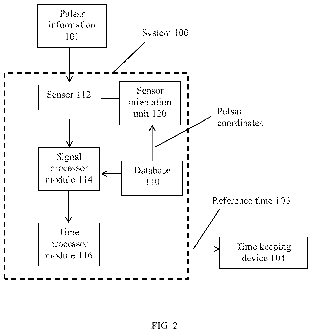
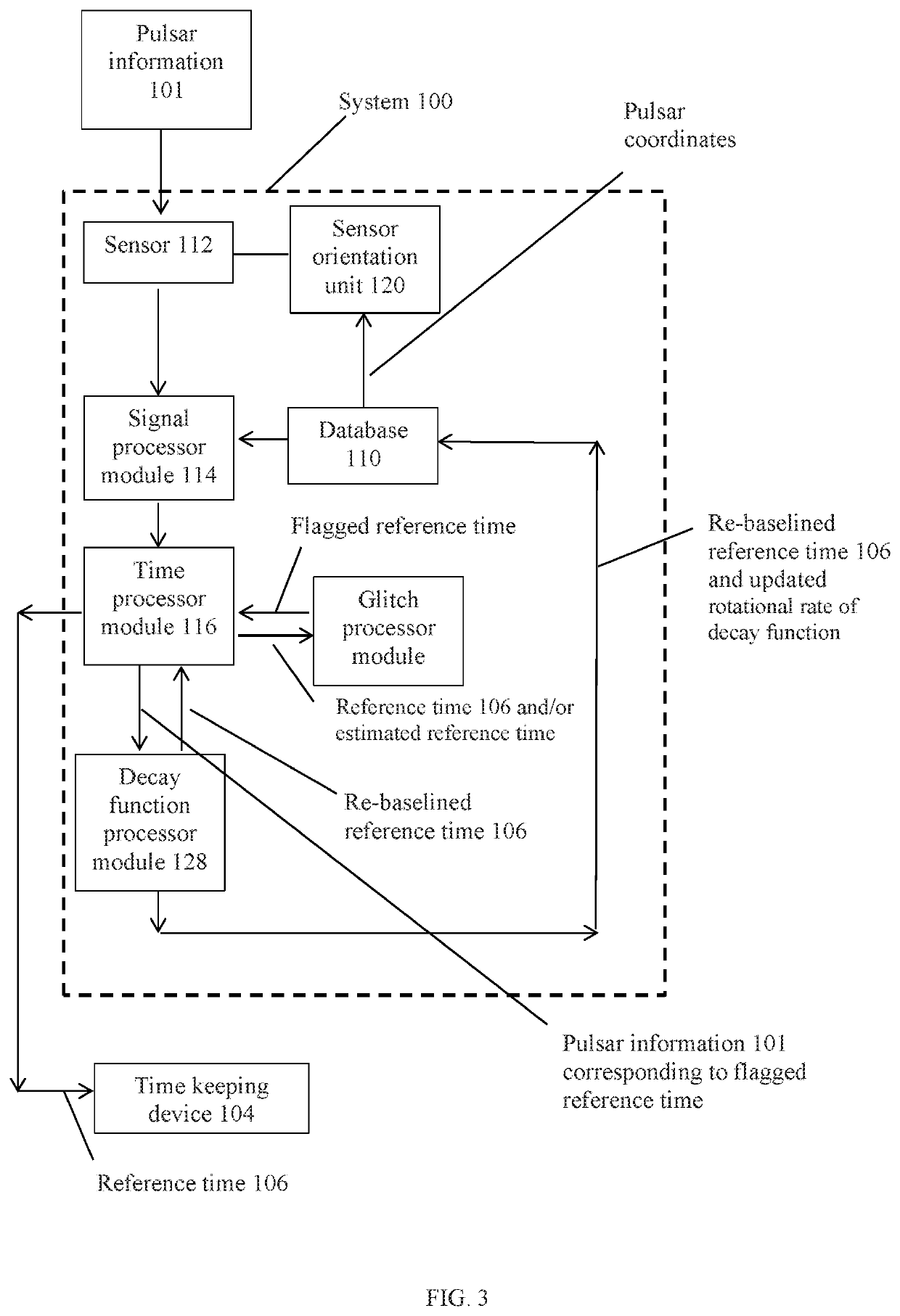
[0016]Referring to FIGS. 1-4, an embodiment of the system 100 can relate to updating a reference time from a decaying rotational period of one or more pulsars 102. A pulsar 102 is a neutron star that emits a beam of electromagnetic radiation. The pulsar 102 also rotates, and as it rotates the beam of electromagnetic radiation is observable as a series of pulses when an observer comes into the path of the rotating beam. The beam rotates at a very stable rate making it suitable for maintaining a frequency standard (or time period) for a time keeping device 104. While the rate of rotation does decay, it does so at a very slow and very predictable rate. An embodiment of the system 100 can be configured to use a previously established reference time of a pulsar 102 and generate an updated reference time 106 based on the observable decaying rotational period of the pulsar 102. Some embodiments can use plural pulsars 102 to improve the accuracy of the updated reference time 106. The update...


PUM


Abstract

Disclosed is a system for updating a reference time from a decaying rotational period of a pulsar. The system can include: a database (DB) configured to store: coordinates for a pulsar; a recorded rate of rotation (RROR) for the pulsar; a rotational rate of decay (RROD) function for the pulsar; and a recorded reference time for the pulsar. A sensor can be configured to collect electromagnetic pulsar radiation from the pulsar and generate sensor data. A signal processor module can be configured to receive the sensor data, generate an observed rate of rotation (OROR) signal profile, generate a current rate of rotation (CROR) for the pulsar from the OROR signal profile, and update the RROR from the CROR. A time processor module can be configured to receive the RROD function and the CROR, and to solve the RROD function to output a reference time of the pulsar.

Description

FIELD[0001]Disclosed are systems and methods that can observe the rotational decay of a pulsar and update a reference time based on the observed rotational decay.BACKGROUND INFORMATION[0002]Known clocks and methods for keeping time involve the use of precision clocks (e.g., pulsar clocks, atomic clocks, quantum clocks, etc.) as a means to “hold” a reference time from which other clocks can be synchronized. For example, a pulsar clock uses the coherence of the pulsar's radiation pulses as the frequency standard for its timekeeping. The frequency standard from the pulsar clock is then used to synchronize other clocks. Known clocks and timekeeping methods are limited in that they rely on a previously configured clock that holds the reference time. This can be problematic for an apparatus that has no access to a previously configured clock (e.g., is too far from the clock) to resynchronize its clock with the reference time.SUMMARY[0003]An embodiment of a system for updating a reference ...

Claims


Application Information

Patent Timeline
IPC IPC(8): G01P3/44G01T1/29G06F17/30G01V3/36
CPCG01T1/2907G06F16/23G01V3/36G01P3/44G01V3/082
Inventor MACLEOD, WILLIAMTER BEEST, JAMESBASS, GIDEON
Owner BOOZ ALLEN HAMILTON INC
Why Eureka
Try Eureka